Chapter 2 discussed the basics for downward-continuation migration in 2-D
using the concept of survey-sinking. For 3-D
the sinking or downward continuation of the wavefield
at depth z (Uz), in midpoint-offset coordinates and in the
frequency-wavenumber domain [![]() ,to a different depth level
,to a different depth level ![]() can be expressed as:
can be expressed as:
| (52) |
the variable ![]() is the Fourier pair for the time
axis, and the variables
is the Fourier pair for the time
axis, and the variables ![]() ,
,![]() and kz are the representation
in the Fourier domain (wavenumber) for the midpoint, offset and
depth axes.
After each depth-propagation step, the resulting wavefield
represents a synthesized dataset with the source and
receiver distribution at the new depth level,
and kz are the representation
in the Fourier domain (wavenumber) for the midpoint, offset and
depth axes.
After each depth-propagation step, the resulting wavefield
represents a synthesized dataset with the source and
receiver distribution at the new depth level, ![]() ,Schultz and Sherwood (1980). For
converted-wave data, the downgoing wavefield is propagated using the P-velocity
(
,Schultz and Sherwood (1980). For
converted-wave data, the downgoing wavefield is propagated using the P-velocity
(![]() ),
whereas the upgoing wavefield is propagated applying
the S-velocity (
),
whereas the upgoing wavefield is propagated applying
the S-velocity (![]() )).
The basic downward-continuation step, for converted waves, is performed by applying the
Double-Square-Root (DSR) equation that in midpoint-offset coordinates is
)).
The basic downward-continuation step, for converted waves, is performed by applying the
Double-Square-Root (DSR) equation that in midpoint-offset coordinates is
 |
||
| (53) |
The common-azimuth downward-continuation operator can then be expressed as follows Biondi and Palacharla (1996):
 |
||
| (54) |
Since common-azimuth data is independent of khy, the integral can be
pulled inside and analytically approximated by the stationary-phase method Bleinstein (1984).
The application of the stationary-phase method is based on a high-frequency approximation,
that is, it assumes that ![]() tends toward infinity.
tends toward infinity.
The expression for ![]() in equation
in equation ![[*]](http://sepwww.stanford.edu/latex2html/cross_ref_motif.gif) comes from substituting the stationary-path approximation into
the expression for the full DSR equation
comes from substituting the stationary-path approximation into
the expression for the full DSR equation ![[*]](http://sepwww.stanford.edu/latex2html/cross_ref_motif.gif) :
:
| |
(55) |
where
 |
(56) |
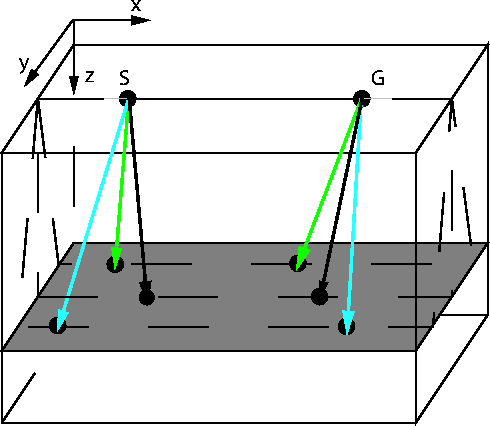
represents the PS stationary path approximation for the double square root equation as a function of khy. To obtain the PS stationay path approximation I follow a geometric interpretation for the PS common-azimuth downward-continuation operator. I adhere to Biondi and Palacharla (1996) demonstration for the equivalence of the stationary phase derivation for the common-azimuth operator and the constraint on the propagation directions of the source rays and receiver rays for the single-mode case.
Figure ![[*]](http://sepwww.stanford.edu/latex2html/cross_ref_motif.gif) shows the ray geometry for the
common-azimuth downward-continuation operator. Notice that
the source ray (psx,psy,psz) and the receiver ray
(prx,pry,psz) lie on the same plane. To fulfill this condition
the components for both rays along the
crossline y axis must be equal.
shows the ray geometry for the
common-azimuth downward-continuation operator. Notice that
the source ray (psx,psy,psz) and the receiver ray
(prx,pry,psz) lie on the same plane. To fulfill this condition
the components for both rays along the
crossline y axis must be equal.
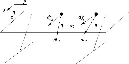
I follow simple geometry to obtain the two crossline y
axis components for the source and receiver rays.
Figure ![[*]](http://sepwww.stanford.edu/latex2html/cross_ref_motif.gif) represents one of the
slanted planes on Figure
represents one of the
slanted planes on Figure ![[*]](http://sepwww.stanford.edu/latex2html/cross_ref_motif.gif) , and
the elements for this geometric derivation.
From the definition of ray parameter, the
component psy for the source ray and the component
pry for the receiver ray are
, and
the elements for this geometric derivation.
From the definition of ray parameter, the
component psy for the source ray and the component
pry for the receiver ray are
 |
 |
 |
||
| (57) |
where dls, dlr are the differential raypath lengths
for the source and receiver ray, respectively, dys
and dyr are the source and receiver crossline
components, as they are illustrated on Figure ![[*]](http://sepwww.stanford.edu/latex2html/cross_ref_motif.gif) .
The components psz for the source ray
and prz for the receiver ray are
.
The components psz for the source ray
and prz for the receiver ray are
 |
||
| (58) |
where dz is the component along the depth axis. This component must be the same for both the source and the receiver ray. This condition also holds for converted waves. The final image forms when all the energy is focused at zero at time equal zero. This is true if both the P-velocity and the S-velocity models are correct. This is a key element for the PS-CAM operator, because of this the converted-wave stationary path does not incorporates any additional parameters.
The final crossline y components for both
the source and receiver rays are the result of
combining the set of equations ![[*]](http://sepwww.stanford.edu/latex2html/cross_ref_motif.gif) with the ones in
with the ones in ![[*]](http://sepwww.stanford.edu/latex2html/cross_ref_motif.gif) , such that
the differential raypath lengths, dls and dlr,
are eliminated.
The components dys and dyr are
, such that
the differential raypath lengths, dls and dlr,
are eliminated.
The components dys and dyr are
 |
||
| (59) |
The condition for the source and receiver rays
lie in the same plane is that both dys and
dyr are the same. By equating the two equations in
![[*]](http://sepwww.stanford.edu/latex2html/cross_ref_motif.gif) I obtain the mathematical expression
of this condition
I obtain the mathematical expression
of this condition
| |
(60) |
To eliminate both psz and prz, from equation ![[*]](http://sepwww.stanford.edu/latex2html/cross_ref_motif.gif) ,
I use the following relationship among the ray parameters:
,
I use the following relationship among the ray parameters:
 |
||
| (61) |
After some mathematical simplifications the stationary path relationship in terms of ray parameters is
 |
(62) |
this equation transforms into equation ![[*]](http://sepwww.stanford.edu/latex2html/cross_ref_motif.gif) by substituting the
wave numbers for the ray parameters.
by substituting the
wave numbers for the ray parameters.
This process just validates the PS common-azimuth downward-continuation operator, I implement PS common-azimuth migration using a split-step algorithm Kessinger (1992). The main difference between the implementation of the PS-CAM operator and the conventional CAM operator is the need of two velocity models.