Next: Migration after regularization
Up: Application to 3D land
Previous: Decimating the field survey
Given the dominantly flat geology of the survey area, the normalization
of the image by the response of a flat event is expected to largely reduce
the effects of varying illumination of the image.
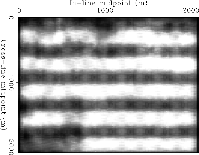
Figure slice-amo-fold shows a time
slice of the AMO fold at 0.71 seconds. The high amplitudes are mostly
distributed along horizontal stripes in the in-line direction (zero-azimuth)
and show direct correlation with the binning fold of the data.
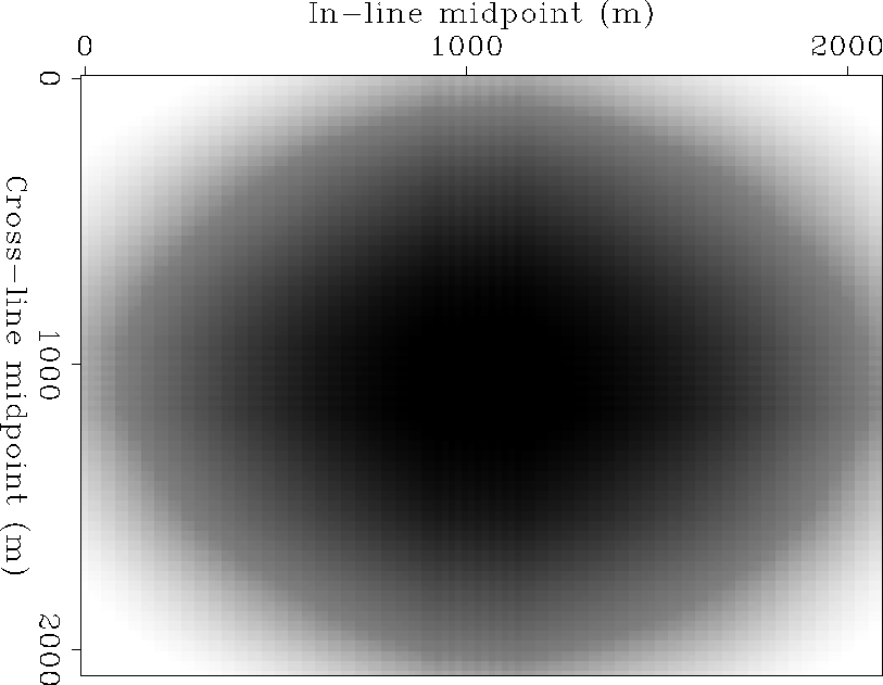
Figure slice-mig-fold shows the migration fold at a depth of 920 m
that corresponds roughly to 0.71 seconds on the time section.
Due to the large aperture of the migration operator compared to the small size
of the survey area, the fold is insensitive to the irregular coverage
of the survey.
It simply displays the distribution of the weights along
the migration impulse response.
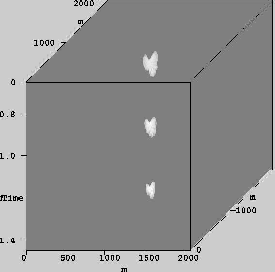
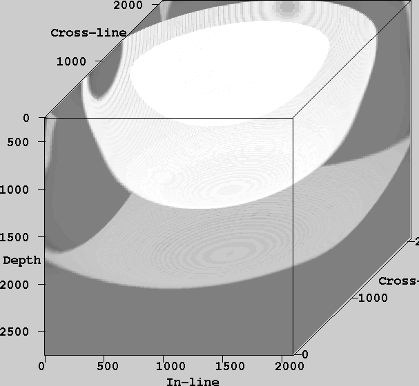
Figures amo-impulse
and mig-impulse show the impulse response of AMO and migration
at different time and depth levels.
While the aperture of AMO is very compact and decreases with time,
the migration aperture is quite large and increases with depth.
At 1.5 km deep it is roughly the size of the entire survey area.
Therefore, normalizing the migrated image tends to simply compensate
for the limited aperture near the edges of the survey
rather than correct for the irregular sampling.
Consequently, I only migrated the first 1.5 km of the data. For
consistency in comparing the results, all images are displayed without
any normalization applied to them.
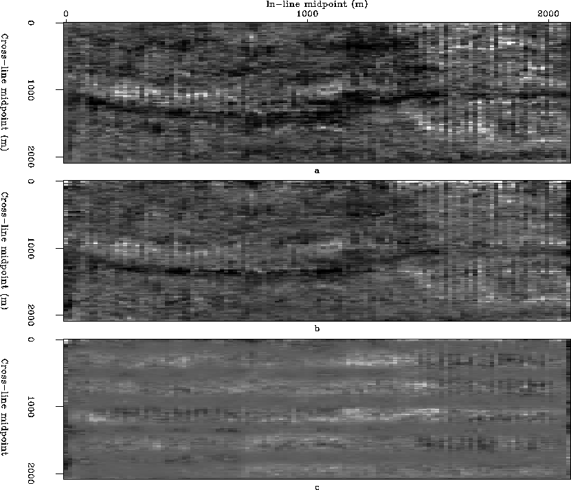
Figure slice-amo1 compares the time slices at .71 seconds, obtained
by un-normalized AMO (Figure slice-amo1a) and normalized AMO
(Figure slice-amo1b). The difference section (Figure slice-amo1c)
clearly displays trends of the AMO fold that were superimposed on the image.
The normalized partial stack, however, shows that few trends of high amplitude
were not correctly
accounted for by the normalization process. The most evident anomalies
tend to occur in zones that originally had low fold coverage and therefore
low signal to noise ratio.
By normalizing the AMO stack, amplitudes in these areas were boosted up
too high in comparison to nice coverage areas.
A simple solution to avoid weighting bad signal higher than good data
is to normalize by a
different function of the fold that provides good trade-off between
multiplicity and signal to noise ratio.
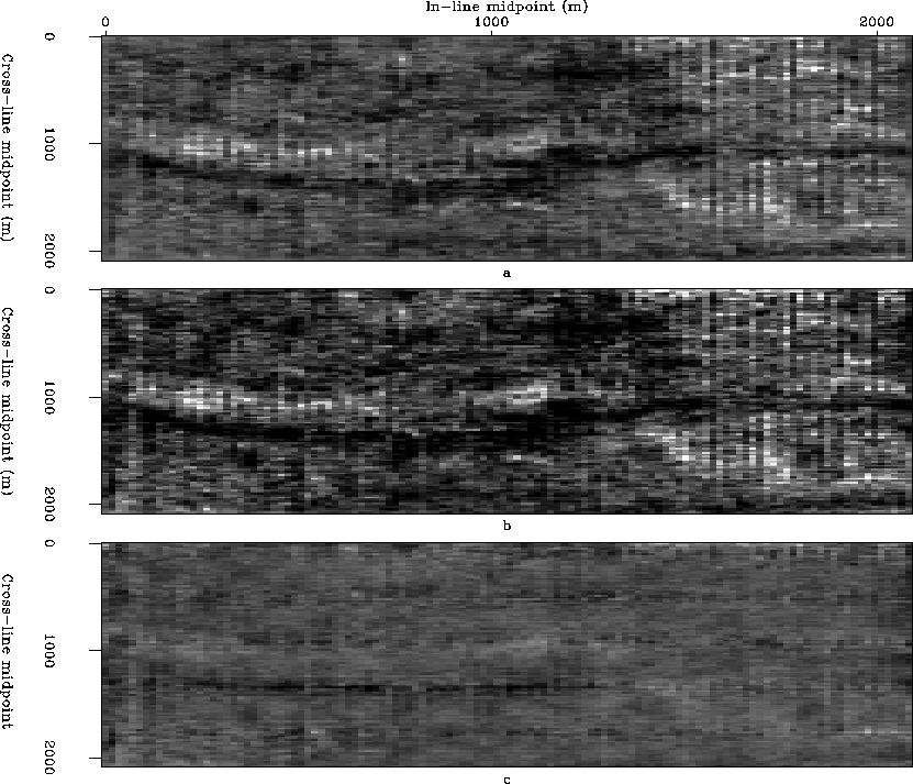
For instance one can normalize by the square root of the
AMO fold (Figure slice-amo05).
Results showed that weighting by some power of the fold between .5 and 1
yields a smooth image with balanced amplitudes.
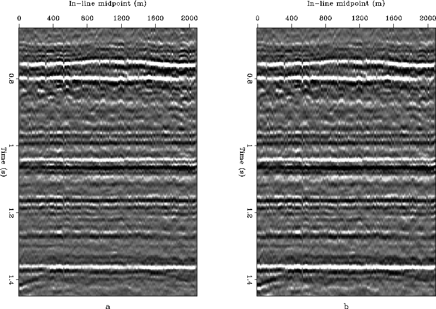
Figure amo-inline displays a window of an in-line section,
located at 1 km along the cross-line axis. Figure amo-inlinea shows
the section obtained by AMO-staking, while Figure amo-inlineb shows
the section obtained by normalizing the AMO-stack. As expected, the
addition of the diagonal scaling to the partial stacking enhances the
continuity of the events and balances the amplitudes along the flat
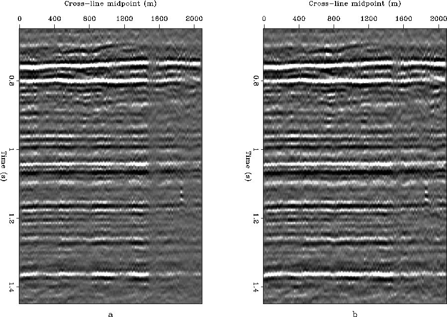
reflections. The improvements are better observed along the cross-line
dimension as shown in Figure amo-crossline. This observation is
consistent with the fact that the fold coverage varies mostly along
the cross-line axis.
slice-amo-fold
Figure 7 AMO fold at 0.71 seconds


 slice-mig-fold
Figure 8 Migration fold at 920 m depth
amo-impulse
Figure 9 AMO impulse response at different time levels for 150m offset continuation and 25 degrees rotation.
mig-impulse
Figure 10 Migration impulse response at depth levels corresponding to the time levels on the figure above.
slice-amo1
Figure 11 Normalizating by the AMO fold: a) un-normalized AMO, b) normalized AMO, c) difference between a) and b)
slice-amo05
Figure 12 Normalizating by the AMO fold to a power of 0.5: a) un-normalized AMO, b) normalized AMO, c) difference between a) and b)
amo-inline
Figure 13 In-line section at 1.km; a) unnormalized AMO, b) normalized AMO
amo-crossline
Figure 14 Cross-line section at 1.km; a) unnormalized AMO, b) normalized AMO
Next: Migration after regularization
Up: Application to 3D land
Previous: Decimating the field survey
Stanford Exploration Project
1/18/2001