


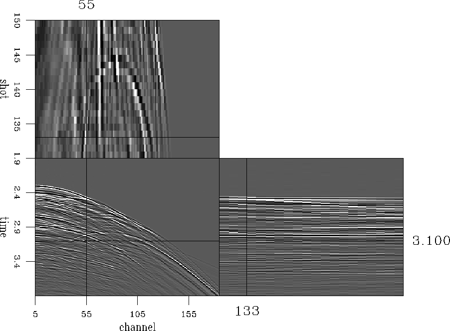
A cube of seismic data with an interesting set of dips was used as a test case. Half the traces were replaced by zeroes and input to some different interpolation schemes based on the equations above.
The important thing is the difference between the true data and the interpolated data we invent to take its place. Naturally, in a real problem the true data are unknown, but it is interesting to see if we can infer anything useful about that difference from the residuals.
Convergence of the filter estimation step for the different implementations is shown in Figure curves.nrp. The curve labels are:
Not surprisingly, the residual of the filter estimation step goes down fastest when there is no restriction on the filters (the Neither curve). While a large filter estimation residual does imply something bad (that the filters do not make a good estimate of the data spectrum), a small filter estimation residual is not necessarily good. In this case, it just means the filters have too many degrees of freedom.
The curves all start off about the same, with the two damped
algorithms flattening out earlier and higher, because
the damping simply prohibits them from putting enough energy in the
filter coefficients to fit much of the data.
The Damped curve looks bad, and continues to look bad in the
later figures as well.
Simply limiting the energy in the filter coefficients is not as
sensible as limiting their roughness, which is what the damping
effectively does for the curve labeled Both.
In the Both curve, damping is applied to the
preconditioned (roughened) variable ![]() , while
in the Damped curve,
the damping is on the actual filter coefficients
, while
in the Damped curve,
the damping is on the actual filter coefficients ![]() .Changing the
.Changing the ![]() to a roughener just reprises the
previous curve, but without the change of variables.
to a roughener just reprises the
previous curve, but without the change of variables.
The residual for the missing data calculation step is shown in Figure curves.nrd. A pleasing thing about all of these curves is that they converge after a handfull of iterations.
|
curves.nrp
Figure 1 Filter calculation residual as a function of iteration. Curves represent different filter calculation schemes. | 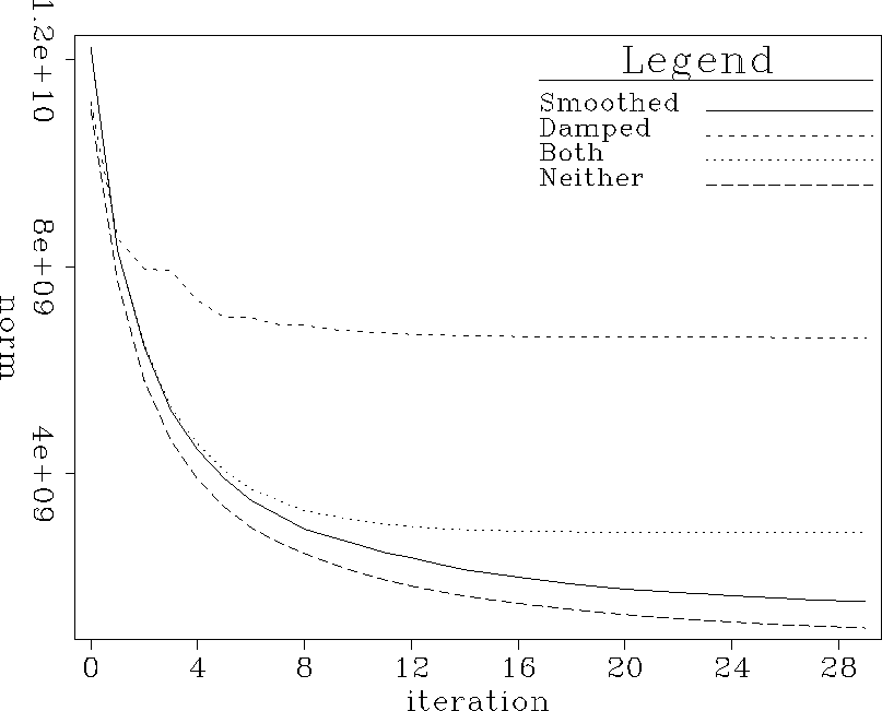 |


|
curves.nrd
Figure 2 Missing data residual as a function of iteration. Curves represent different filter calculation schemes. | 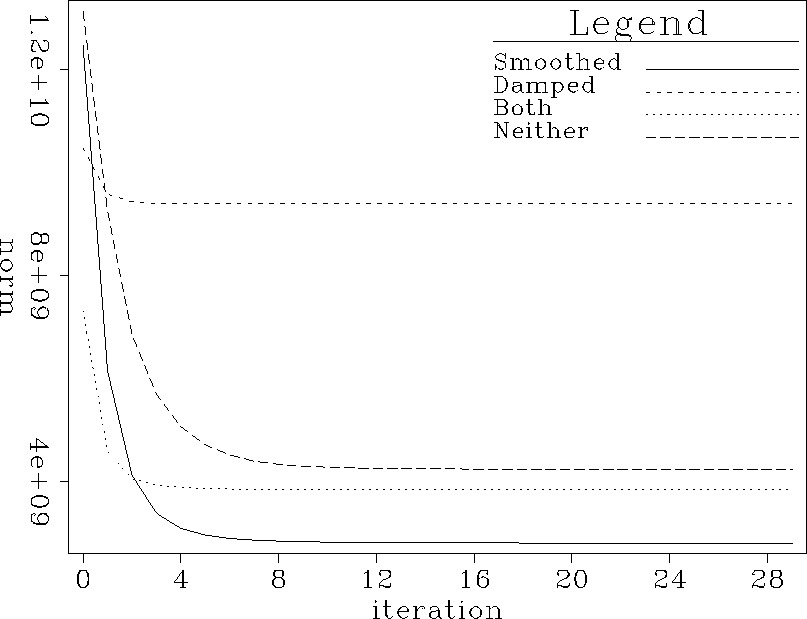 |
Figure curves.nm shows the real quantity of interest. Each curve is the norm of the difference between the interpolated data and the true data as a function of iteration in the second step of the interpolation. In every case (though just barely in a couple), the difference increases at later iterations. In principle the true data are unknown, so there is no reason for the difference not to increase. The PEFs are certain not to be perfect, and will eventually begin to add in some undesirable components. The misfit starts to go up after the residual from Figure curves.nrd has bottomed out.
Figure curves.nm.filtniter shows the same curve, along with several others that all use the same algorithm (preconditioning, no damping), but different numbers of iterations, to calculate PEFs. With many iterations, the minimum value on a given curve increases. Too many iterations, either in calculating the filter coefficients or in calculating the missing data, degrades the result. In the case of the missing data iterations, the residual has bottomed out, as shown in Figure curves.nrd.30, which plots the data residual and norm of the misfit between interpolated and true data, as a function of iteration. In the case of the filter coefficient iterations, it is not obvious when to stop.
Damping with the appropriate value of ![]() helps.
Figure curves.nm.slightdamp.fn shows the same sorts of
curves as Figure curves.nm.filtniter, with a reasonable
helps.
Figure curves.nm.slightdamp.fn shows the same sorts of
curves as Figure curves.nm.filtniter, with a reasonable
![]() .Here the curves are fairly close together, so that running
too many filter calculation iterations does not degrade the
final result too much.
The wrong value of
.Here the curves are fairly close together, so that running
too many filter calculation iterations does not degrade the
final result too much.
The wrong value of ![]() causes the same problems as
the wrong number of iterations without damping, however.
Figure curves.nm.muchdamp shows the misfit between
the true and interpolated data for different values of
causes the same problems as
the wrong number of iterations without damping, however.
Figure curves.nm.muchdamp shows the misfit between
the true and interpolated data for different values of ![]() .With the damping, you need to find the correct value of
.With the damping, you need to find the correct value of ![]() ,and without it, you need to find the correct number of iterations
for calculating the PEF coefficients.
Results tend to be somewhat less sensitive to
,and without it, you need to find the correct number of iterations
for calculating the PEF coefficients.
Results tend to be somewhat less sensitive to ![]() ,and choosing
,and choosing ![]() to make the two components of the
filter calculation residual roughly balance is usually
a safe choice Lomask (1998).
to make the two components of the
filter calculation residual roughly balance is usually
a safe choice Lomask (1998).
|
curves.nm
Figure 3 Norm of the misfit between the true data and the interpolated data. Horizontal axis displays number of iterations in the missing data calculation step. Curves represent different filter calculation schemes. | 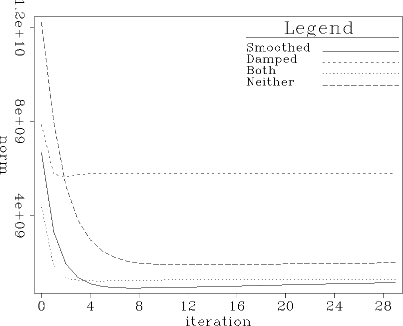 |
|
curves.nm.filtniter
Figure 4 Norm of the misfit between the true data and the interpolated data. Horizontal axis displays number of iterations in the missing data calculation step. Curves represent different numbers of iterations in the filter calculation step. | 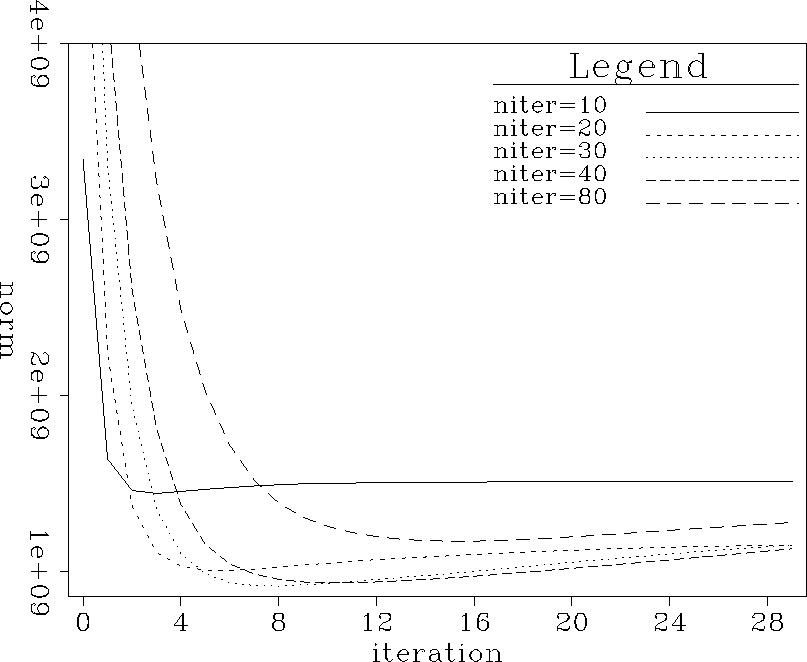 |
|
curves.nrd.30
Figure 5 Norm of the missing data residual and the misfit between true and interpolated data. Misfit rises after the missing data residual flattens out. | 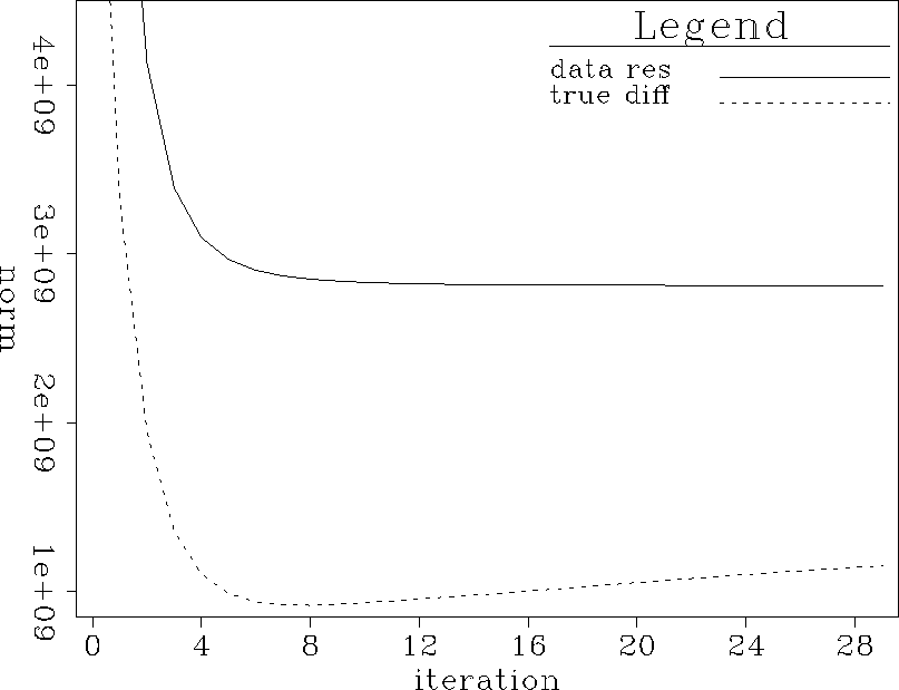 |
|
curves.nm.slightdamp.fn
Figure 6 Norm of the misfit between true data and interpolated data. Curves represent different numbers of iterations in the filter calculation step. | 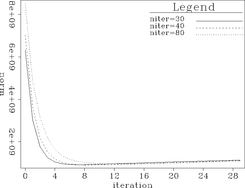 |
|
curves.nm.muchdamp
Figure 7 Norm of the misfit between true data and interpolated data. Curves represent different amounts of damping. | 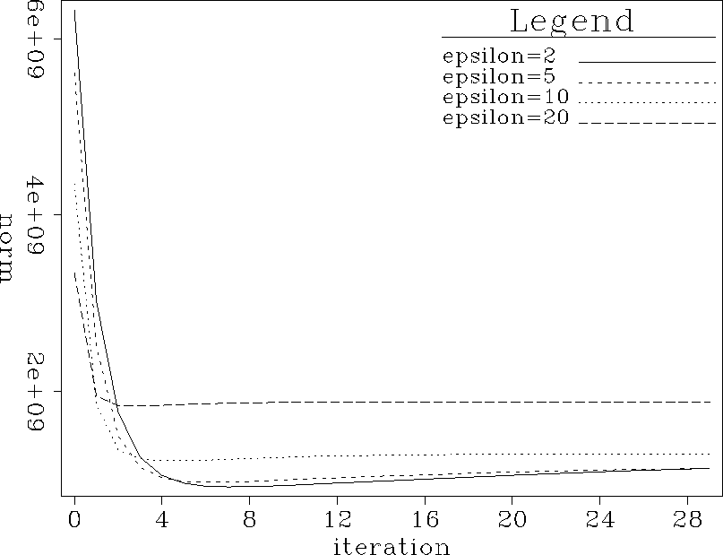 |
 |