


![[*]](http://sepwww.stanford.edu/latex2html/cross_ref_motif.gif) :
:
  DO IZ=1,NZ
      A = SPREAD( -AA, DIM = 1, NCOPIES = NX )
      B = SPREAD( 1.+2.*AA, DIM = 1, NCOPIES = NX )
      C = SPREAD( -AA, DIM = 1, NCOPIES = NX )
C Compute right-hand side
      FORALL(J=1:NW) CD(1,J) = AA(J)*CP(2,J) + (1.-2.*AA(J))*CP(1,J)
      FORALL(J=1:NW) CD(NX,J) = AA(J)*CP(NX-1,J) + (1.-2.*AA(J))*CP(NX,J)
      FORALL(I=2:NX-1,J=1:NW) CD(I,J) = AA(J)*CP(I+1,J) +
     &   (1.-2.*AA(J))*CP(I,J) + AA(J)*CP(I-1,J)
C Tridiagonal solver
      CALL GEN_TRIDIAG_SOLVE( CD,A,B,C,ONE,TOL,IER)
C Lens term
      CP = CD * SHIFTS
C Imaging
      P(:,IZ) = SUM(REAL(CP), DIM = 2)
   ENDDO
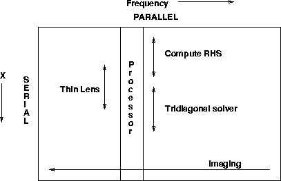
Both programs have the four key ingredients of a 2-D implicit finite-difference migration: computing the right-hand side, solving the tridiagonal system, applying the thin lens term, and imaging.
A major difference between the two programs is that on the CM, there is no
loop over frequencies. All frequencies
are solved in parallel. Each CM processor sets up and solves
the tridiagonal system of equations for one frequency.
This mapping of the problem onto the processors of the machine
is attractive because three of the four components in the algorithm
(all except imaging) will then require no inter-processor communication,
which should be avoided where possible on the Connection Machine.
Figure illustrates this mapping of the problem onto
the hardware of the Connection Machine.
 |

For best performance, we need to have enough frequencies to keep all processors busy. On a 4K (single bit) processor machine, there are 128 floating point processors. For hardware reasons, we need to have at least 4 times 128 or 512 frequencies to achieve best performance.
An alternative mapping of the problem is possible. We could make both the frequency and x axes parallel. This is a good thing to do for small problems, where we do not have enough frequencies to keep all processors busy with a (parallel, serial) ordering. A drawback to a (parallel, parallel) ordering is that all parts of the program will then require inter-processor communication. So if there are enough frequencies, it seems that the (parallel, serial) ordering is the way to go.
The mapping is specified by LAYOUT compiler directives. Here are the array declarations for the Fortran 90 code fragment shown above:
REAL P( NX,NZ )
COMPLEX CP( NX,NW )
COMPLEX A( NX,NW )
COMPLEX B( NX,NW )
COMPLEX C( NX,NW )
COMPLEX CD( NX,NW )
COMPLEX AA( NW )
COMPLEX SHIFTS( NX,NW )
and here are the associated layout directives:
CMF$LAYOUT P(:SERIAL,:NEWS)
CMF$LAYOUT CP(:SERIAL,:NEWS)
CMF$LAYOUT A(:SERIAL,:NEWS)
CMF$LAYOUT B(:SERIAL,:NEWS)
CMF$LAYOUT C(:SERIAL,:NEWS)
CMF$LAYOUT CD(:SERIAL,:NEWS)
CMF$LAYOUT SHIFTS(:SERIAL,:NEWS)
CMF$LAYOUT AA(:NEWS)
Changing all instances of SERIAL in the layout directives to NEWS would effect a (parallel, parallel) ordering.
The tridiagonal solver routine GEN_TRIDIAG_SOLVE
solves (in this case) NW tridiagonal systems, each of length NX,
in parallel. We supply NW copies of the three diagonal matrices.
The SPREAD intrinsic function creates the necessary copies.
The routine GEN_TRIDIAG_SOLVE is a parallel tridiagonal solver
from the Connection Machine Scientific Software Library (CMSSL).
On the Convex, I did not use the routine ctris shown in
the Ratfor code example, but rather a well-vectorized tridiagonal
solver from the Convex VECLIB vector processing library. This
insures as fair a comparison between the two machines as possible.