Next: IMAGING CONDITION AND LOCAL
Up: OVERVIEW OF THE MIGRATION
Previous: step 2
Backward time propagation of the recorded particle-displacement field and
 and its time-derivative
  , starting at the end
time of the shot record and ending at time zero. These wavefields are
introduced as time-dependent boundary conditions at z=0. Simultaneously with
this backward propagation, this step also computes the lag zero of
the correlation between the downgoing scalar field u(x,z) and the upcoming
scalar field w(x,z).
For each time step the following arrays are computed:
, starting at the end
time of the shot record and ending at time zero. These wavefields are
introduced as time-dependent boundary conditions at z=0. Simultaneously with
this backward propagation, this step also computes the lag zero of
the correlation between the downgoing scalar field u(x,z) and the upcoming
scalar field w(x,z).
For each time step the following arrays are computed:
-
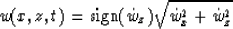
Scalar upcoming particle-displacement field
-
Unit vector in the group propagation direction of the upcoming wavefield

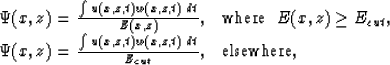
Finally, the reflection coefficient image is computed as
and the local Snell parameter image as
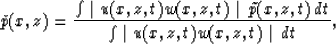
where  is computed from
  and
and  ,as described in the next section.
Next: IMAGING CONDITION AND LOCAL
Up: OVERVIEW OF THE MIGRATION
Previous: step 2
Stanford Exploration Project
12/18/1997