


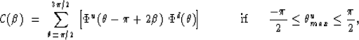
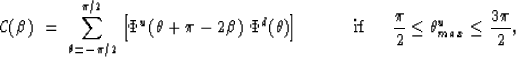
 |
||
| (14) |
I demonstrate below that these relations give the correct estimation
of the propagation direction for the incident wavefield.
Figure ![[*]](http://sepwww.stanford.edu/latex2html/cross_ref_motif.gif) shows the wavefield amplitude along the line defined
by the gradient of the potential field.
shows the wavefield amplitude along the line defined
by the gradient of the potential field.
|
wavedir
Figure 11 A representation of the amplitude of potential field along the gradient direction. |  |

The gradient of the potential field gives the direction, but not the sense of propagation. Any point A in the interval between points 1 and 2 in the figure will have a positive gradient and any point B in the interval between points 2 and 3 will have a negative gradient. Since the propagation direction is positive (to the right) point A will have a negative time derivative, while point B will have a positive time derivative. If the propagation direction was negative (to the left), then the gradients would remain unchanged, while the time derivatives would switch sign. As a result, the product of the gradient and the time derivative at any point will have the opposite sign of the propagation direction.
CORRELATION INTERVALS FOR THE PLANE-WAVE DECOMPOSITION
Figure shows a snapshot of a wavefield at the
particular time and location where a wavefront is being transmitted/converted,
and reflected at an interface. No conversion is observed because only the P
wave potential field is displayed.
To implement the plane-wave decomposition imaging criterion requires
the computation of the slant-stacks around all points in the grid
for the upcoming and the downgoing wavefields, at regular angle intervals.
These stacks correspond to a semi-plane-wave decomposition
around each point because they are computed from (not across) the grid points.
|
wavesplit
Figure 12 Snap-shot of a wavefield propagating through an interface. The incident and transmitted wavefronts propagate downward while the reflected wavefront propagates upward. All three wavefronts meet at the point of the interface where the partition takes place at that particular time. | 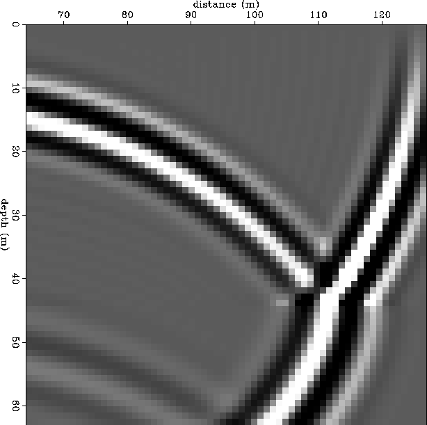 |
Lets consider the two functions ![]() and
and ![]() ,
corresponding, respectively, to the stacks of the upcoming and downgoing
wavefields around the intersection
point of the three wavefronts (incident, transmitted and reflected) in
Figure .
While
,
corresponding, respectively, to the stacks of the upcoming and downgoing
wavefields around the intersection
point of the three wavefronts (incident, transmitted and reflected) in
Figure .
While ![]() will have only one maximum, in the direction
tangent to the reflected wavefront at that point,
will have only one maximum, in the direction
tangent to the reflected wavefront at that point, ![]() will
have two local maxima; one in the direction tangent to the incident
wavefront and one in the direction tangent to the transmitted wavefront.
An crucial step in this imaging criterion is the selection of the
proper subdomain
will
have two local maxima; one in the direction tangent to the incident
wavefront and one in the direction tangent to the transmitted wavefront.
An crucial step in this imaging criterion is the selection of the
proper subdomain ![]() of the distribution
of the distribution ![]() where the
maximum associated with the incident wave is located.
where the
maximum associated with the incident wave is located.
First it is necessary to find the angle ![]() for
which
for
which ![]() is maximum:
is maximum:
![]()
The following rules are applied in the analysis:
Figure shows four diagrams, each one corresponding
to a different quadrant location for ![]() . The dark
bars in each diagram refers to the limit directions of the
reflected wavefront (i.e.,
. The dark
bars in each diagram refers to the limit directions of the
reflected wavefront (i.e., ![]() ) in
each quadrant and the arrows indicate the only possible propagation
direction for this wavefront.
) in
each quadrant and the arrows indicate the only possible propagation
direction for this wavefront.
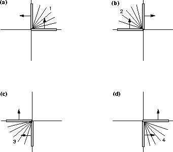 |
Lets consider each of the four possibilities:
![]()
![]()
![]()
![]()
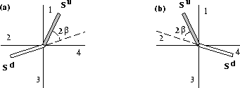
The above relations can be summarized as
![]()
![]()
Figure is a graphical representation of theses relations.
When the reflected wavefront is located in the first or fourth
quadrants (dark bar in -a) the incident wavefront
must be in the second or third quadrants (white bar). When the
reflected wavefront is located in the second or third
quadrants (dark bar in -b) the incident wavefront
must be in the first or fourth quadrants (white bar).
As indicated in the figure the angle between the direction
of the two wavefronts is equal to twice the angle of incidence.
 |
Using the above relations, the correlation between the two distributions
![]() and
and ![]() is will be given by
is will be given by
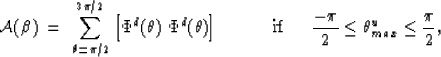
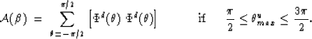
The reflectivity estimation for that particular time would be
given by the ratio ![]() .
.