

Next: Examples
Up: Ji and Claerbout: Migration
Previous: DATUMING AND DEPTH MIGRATION
A migration operator is conjugate to the corresponding forward
modeling operator (Claerbout, 1992).
In order to find the conjugate operator,
the linear forward modeling operator must be found first.
For the sake of simplicity, we formulate the modeling algorithm
from the datuming viewpoint, which requires only an extrapolation operator.
The migration operator can be obtained
by changing the input from the wavefield to the subsurface image
and adding the imaging and transformation operator
into the extrapolation operator.
To start, we formulate a simple modeling algorithm
using phase-shift extrapolation when the recording surface is not flat.
For simplicity, the number of geophone groups
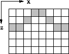
on an irregular surface is eight as illustrated in Figure ![[*]](http://sepwww.stanford.edu/latex2html/cross_ref_motif.gif) .
.
syngeometry
Figure 2 Synthetic surface recording geometry.
Solid squares represent geophone location on an
undulating surface.
|
|  |

The wavefield recorded at each geophone is
the wavefield propagated up to the depth level
where the geophones are located.
Therefore, the modeling can be formulated by propagating
the wavefield upward without regard
for the irregular surface boundary.
Then at each altitude, various portions
(shaded in Figure ![[*]](http://sepwww.stanford.edu/latex2html/cross_ref_motif.gif) ) are extracted from the wavefield.
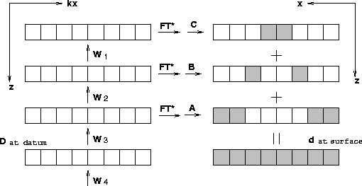
The sum of these extracted portions makes up the wavefield
along the irregular surface.
Figure
) are extracted from the wavefield.
The sum of these extracted portions makes up the wavefield
along the irregular surface.
Figure ![[*]](http://sepwww.stanford.edu/latex2html/cross_ref_motif.gif) explains this modeling algorithm
in the datuming sense.
explains this modeling algorithm
in the datuming sense.
tpmdlschm1
Figure 3 Modeling scheme 1: The schematic diagram for
exploding reflector modeling when the surface is not flat.
Wj represents the upward propagating operator
at the j-th depth level shown in equation (2),
FT* represents the inverse Fourier transform.
A, B and C are spatial filter shown in equation (3).

In order to find the conjugate operator of the algorithm
shown in Figure ![[*]](http://sepwww.stanford.edu/latex2html/cross_ref_motif.gif) , the algorithm must be
written down in algebraic form.
The algebraic representation for the forward modeling scheme in
Figure
, the algorithm must be
written down in algebraic form.
The algebraic representation for the forward modeling scheme in
Figure ![[*]](http://sepwww.stanford.edu/latex2html/cross_ref_motif.gif) is given by
is given by
| ![\begin{displaymath}
\left[
\begin{array}
{ccc}
A&B&C\end{array}\right]
\left[
\b...
...t]
=
\left[
\begin{array}
{c}
d_{\rm surface}\end{array}\right]\end{displaymath}](img1.gif) |
(1) |
where  and
and  represent
the wavefield in the frequency-wavenumber domain at the datum
just below the deepest geophone location and
the wavefield in the frequency-space domain at the nonflat surface,
respectively, and where A,B, and C are masking operators
defined in Figure
 ![[*]](http://sepwww.stanford.edu/latex2html/cross_ref_motif.gif) (and later in equation (2)).
Equation (1) shows that the modeling can be decomposed into three steps.
The first step is the extrapolation step.
The first matrix multiplied to the input has three diagonal matrices,
U1, U2 and U3, along its column for the given model and
the number of matrices will change as the topography changes.
The matrix Uj consists of j operators, from Wj to W1,
which do extrapolation by phase shift
from j-th depth level to the surface.
The extrapolation operator at each depth level Wj is
a diagonal matrix such as:
(and later in equation (2)).
Equation (1) shows that the modeling can be decomposed into three steps.
The first step is the extrapolation step.
The first matrix multiplied to the input has three diagonal matrices,
U1, U2 and U3, along its column for the given model and
the number of matrices will change as the topography changes.
The matrix Uj consists of j operators, from Wj to W1,
which do extrapolation by phase shift
from j-th depth level to the surface.
The extrapolation operator at each depth level Wj is
a diagonal matrix such as:
![\begin{displaymath}
\left[
\begin{array}
{cccccccc}
\exp^{ik_{z_j}\Delta z}&.&.&...
...&.\\ .&.&.&.&.&.&.&\exp^{ik_{z_j}\Delta z}\\ \end{array}\right]\end{displaymath}](img5.gif)
where kz is a function of frequency( ) and
horizontal wavenumber(kx), defined by the dispersion relation
of the acoustic wave equation.
Some of these elements will be set to zero instead of
  if kz falls into an evanescent branch of the dispersion relation.
The second step is to inverse Fourier transform along the horizontal axis x
in preparation for the third step in which the wavefield is picked
where a geophone is located at each depth level.
The operator applied in the third step in equation (1)
consists of three diagonal matrices
on each of which is designed to pick out the wavefield
at the geophone location on each depth level.
For the synthetic model given in Figure
 ![[*]](http://sepwww.stanford.edu/latex2html/cross_ref_motif.gif) ,
A, B and C have the following form:
,
A, B and C have the following form:
![\begin{displaymath}
A=
\left[
\begin{array}
{cccccccc}
1& & & & & & & \\ &1& & ...
...&1& & \\ & & & & & &.& \\ & & & & & & &.\\ \end{array}\right]\end{displaymath}](img8.gif)
| ![\begin{displaymath}
\rm and
\quad
C=
\left[
\begin{array}
{cccccccc}
.& & & & & ...
...&.& & \\ & & & & & &.& \\ & & & & & & &.\\ \end{array}\right]\end{displaymath}](img9.gif) |
(2) |
where dots represent zeros.
Now, the datuming operator can be easily found
by transposing and taking the complex conjugate of the forward operator
shown in equation (1).
Therefore, we get the datuming operator for the data gathered
on an irregular surface as
| ![\begin{displaymath}
\left[
\begin{array}
{ccc}
U_1^T&U_2^T&U_3^T\end{array}\righ...
...}\right]
=
\left[
\begin{array}
{c}
D_{datum}\end{array}\right]\end{displaymath}](img10.gif) |
(3) |
where FT is the Fourier transform along the horizontal axis and
WjT represents downward phase-shift operator at each depth level.
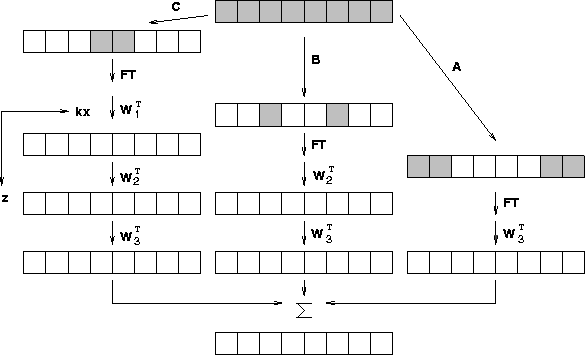
Equation (3) says that the conjugate operator
of wavefield picking at several depth levels is
the summation of the wavefields
which are separately extrapolated from those depth levels
at the point where the wavefields were picked.
Figure ![[*]](http://sepwww.stanford.edu/latex2html/cross_ref_motif.gif) shows a schematic of this datuming operator.
tpmigschm1
shows a schematic of this datuming operator.
tpmigschm1
Figure 4 Datuming scheme 1 :
Schematic diagram for datuming
when the surfaces are irregular as the conjugate operator
to modeling scheme 1.
W1T represents the downward propagation operator
at each depth level.


Next: Examples
Up: Ji and Claerbout: Migration
Previous: DATUMING AND DEPTH MIGRATION
Stanford Exploration Project
11/17/1997
![[*]](http://sepwww.stanford.edu/latex2html/cross_ref_motif.gif) .
.
![[*]](http://sepwww.stanford.edu/latex2html/cross_ref_motif.gif) .
.

![[*]](http://sepwww.stanford.edu/latex2html/cross_ref_motif.gif) ) are extracted from the wavefield.
The sum of these extracted portions makes up the wavefield
along the irregular surface.
Figure
) are extracted from the wavefield.
The sum of these extracted portions makes up the wavefield
along the irregular surface.
Figure ![[*]](http://sepwww.stanford.edu/latex2html/cross_ref_motif.gif) explains this modeling algorithm
in the datuming sense.
explains this modeling algorithm
in the datuming sense.

![[*]](http://sepwww.stanford.edu/latex2html/cross_ref_motif.gif) , the algorithm must be
written down in algebraic form.
The algebraic representation for the forward modeling scheme in
Figure
, the algorithm must be
written down in algebraic form.
The algebraic representation for the forward modeling scheme in
Figure ![[*]](http://sepwww.stanford.edu/latex2html/cross_ref_motif.gif) is given by
is given by
![\begin{displaymath}
\left[
\begin{array}
{ccc}
A&B&C\end{array}\right]
\left[
\b...
...t]
=
\left[
\begin{array}
{c}
d_{\rm surface}\end{array}\right]\end{displaymath}](img1.gif)

![[*]](http://sepwww.stanford.edu/latex2html/cross_ref_motif.gif) (and later in equation (2)).
Equation (1) shows that the modeling can be decomposed into three steps.
The first step is the extrapolation step.
The first matrix multiplied to the input has three diagonal matrices,
U1, U2 and U3, along its column for the given model and
the number of matrices will change as the topography changes.
The matrix Uj consists of j operators, from Wj to W1,
which do extrapolation by phase shift
from j-th depth level to the surface.
The extrapolation operator at each depth level Wj is
a diagonal matrix such as:
(and later in equation (2)).
Equation (1) shows that the modeling can be decomposed into three steps.
The first step is the extrapolation step.
The first matrix multiplied to the input has three diagonal matrices,
U1, U2 and U3, along its column for the given model and
the number of matrices will change as the topography changes.
The matrix Uj consists of j operators, from Wj to W1,
which do extrapolation by phase shift
from j-th depth level to the surface.
The extrapolation operator at each depth level Wj is
a diagonal matrix such as:
![\begin{displaymath}
\left[
\begin{array}
{cccccccc}
\exp^{ik_{z_j}\Delta z}&.&.&...
...&.\\ .&.&.&.&.&.&.&\exp^{ik_{z_j}\Delta z}\\ \end{array}\right]\end{displaymath}](img5.gif)
![[*]](http://sepwww.stanford.edu/latex2html/cross_ref_motif.gif) ,
A, B and C have the following form:
,
A, B and C have the following form:
![\begin{displaymath}
A=
\left[
\begin{array}
{cccccccc}
1& & & & & & & \\ &1& & ...
...&1& & \\ & & & & & &.& \\ & & & & & & &.\\ \end{array}\right]\end{displaymath}](img8.gif)
![\begin{displaymath}
\rm and
\quad
C=
\left[
\begin{array}
{cccccccc}
.& & & & & ...
...&.& & \\ & & & & & &.& \\ & & & & & & &.\\ \end{array}\right]\end{displaymath}](img9.gif)
![\begin{displaymath}
\left[
\begin{array}
{ccc}
U_1^T&U_2^T&U_3^T\end{array}\righ...
...}\right]
=
\left[
\begin{array}
{c}
D_{datum}\end{array}\right]\end{displaymath}](img10.gif)

![[*]](http://sepwww.stanford.edu/latex2html/cross_ref_motif.gif) shows a schematic of this datuming operator.
shows a schematic of this datuming operator.
