

Next: 2-D results
Up: SYNTHETIC DATA EXAMPLES
Previous: SYNTHETIC DATA EXAMPLES
Figure ![[*]](http://sepwww.stanford.edu/latex2html/cross_ref_motif.gif) shows a representative shot gather.
Realistic acquisition
parameters were modeled as follows. The shot radiation pattern was modeled
as
shows a representative shot gather.
Realistic acquisition
parameters were modeled as follows. The shot radiation pattern was modeled
as  for a near-surface impulsive source, the receiver radiation
pattern was modeled as
  which emulates the receiver group
and vertical component amplitude effect. The geometrical spreading was
modeled proportional to r-1.5 to simulate typical v(z) spreading.
Each of 120 60-fold shots were modeled with a 120-trace cable,
a minimum and maximum receiver offset of 0.3 and 3.3 km,
and a 25 m receiver group spacing. Total trace length is
4.0 s at a 4 ms sample interval, and the data are bandpassed to the
10-50 Hz spectral range.
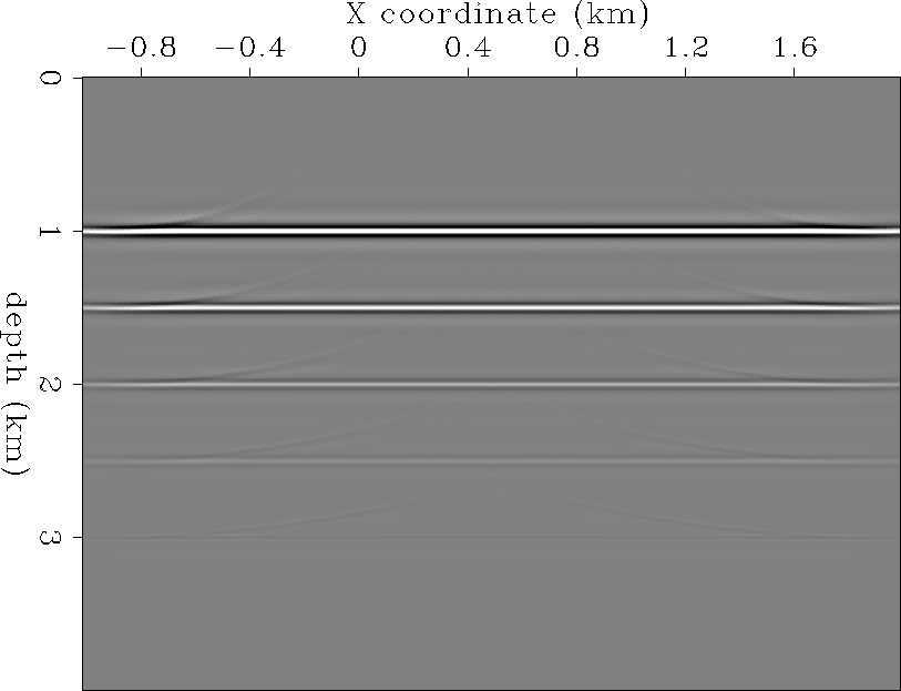
Figure ![[*]](http://sepwww.stanford.edu/latex2html/cross_ref_motif.gif) shows the result of a standard prestack migration.
The reflection amplitudes are meaningless because of the migration
stacking bias along prestack hyperbolas with varying angle-dependent
reflectivity amplitudes. The shallowest horizontal reflector is strongly
positive due to the migration stacking bias for
shows the result of a standard prestack migration.
The reflection amplitudes are meaningless because of the migration
stacking bias along prestack hyperbolas with varying angle-dependent
reflectivity amplitudes. The shallowest horizontal reflector is strongly
positive due to the migration stacking bias for  ; the
recording geometry gives an illumination aperture of 10-60.
As the reflector depth increases, the recording geometry illumination aperture
decreases also. This has the effect of decreasing the stacked reflector
amplitudes with increasing depth, because the migration aperture stack is
increasingly centered about both sides of the 15 polarity reversal,
effectively summing to zero.
Figure ![[*]](http://sepwww.stanford.edu/latex2html/cross_ref_motif.gif) shows the l2 estimation of
shows the l2 estimation of  for a common reflection point (CRP), or ``iso-x'' gather.
This picture is the l2 depth-migrated equivalent of an NMO and
amplitude-corrected CMP gather. Note the correct polarity reversal
with increasing offset. Figure
 ![[*]](http://sepwww.stanford.edu/latex2html/cross_ref_motif.gif) is the associated
is the associated
 reflection angle gather. Do not be alarmed by
the apparent wild variation in this figure - it is an artifact of an
artificial synthetic data set which contains a very sparse set of reflections.
Elsewhere in this report, I show very stable reflection angle estimates
for a real data pilot study over a producing gas reservoir in the Gulf of
Mexico, using this same method. Figure
 ![[*]](http://sepwww.stanford.edu/latex2html/cross_ref_motif.gif) is an overlay
of the reflection angles (contoured in 5 increments), on top of
the
is an overlay
of the reflection angles (contoured in 5 increments), on top of
the  estimates. Note that the 15 contour tracks the
correct polarity crossing almost exactly, at each reflector depth.
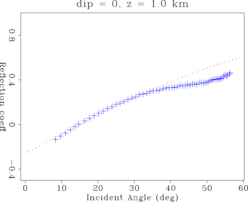
Figure ![[*]](http://sepwww.stanford.edu/latex2html/cross_ref_motif.gif) shows the l2 estimation of
shows the l2 estimation of  on the z = 1.0 km reflector at a common reflection point (CRP).
Since the model is 1-D, these figures are independent of surface location,
and depend only on source-receiver offset.
The l2 estimates (crosses) closely match the
correct values (dots). There is an increasing error for angles beyond
about 35 which is related to spatial aliasing of the shallow migration
operator impulse response. I was unsuccessful at attempts to anti-alias
this operator while simultaneously preserving wide-angle reflection
amplitude estimates.
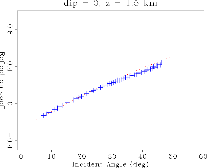
Figure ![[*]](http://sepwww.stanford.edu/latex2html/cross_ref_motif.gif) shows a much improved l2 estimate of
shows a much improved l2 estimate of  on the z = 1.5 km reflector. This depth is apparently below the
spatial-aliasing limit, and so achieves accurate amplitude values for
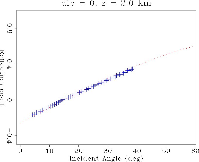
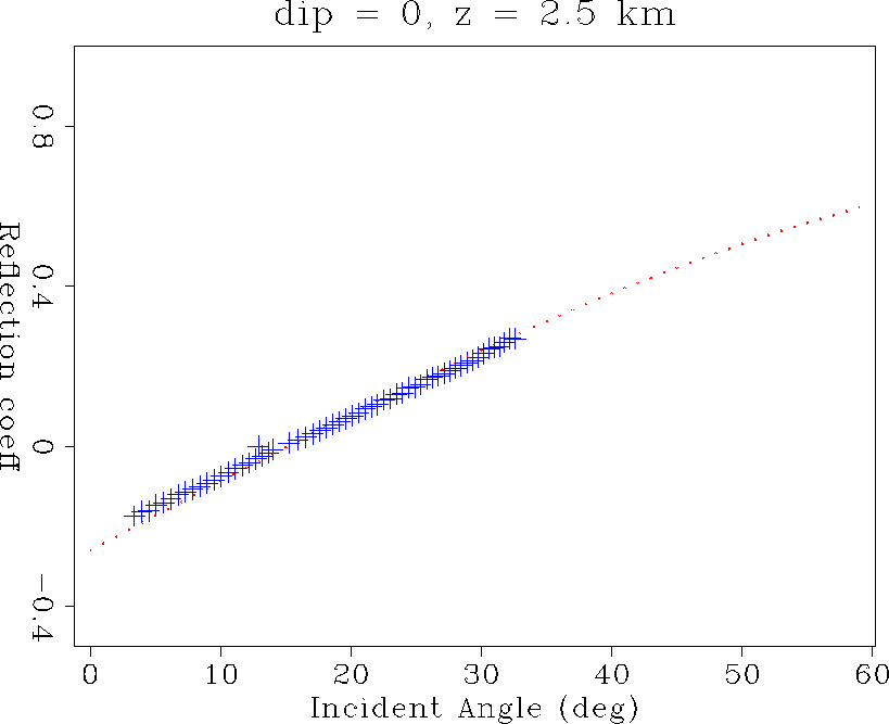
the entire 5-45 illumination aperture. Similarly, Figures
![[*]](http://sepwww.stanford.edu/latex2html/cross_ref_motif.gif) to
to ![[*]](http://sepwww.stanford.edu/latex2html/cross_ref_motif.gif) show very accurate amplitude recovery
of the polarity reversal AVO curve over all recording geometry apertures.
Note in particular that the l2 nature of the inverse solution is
compensating for finite recording aperture, since amplitudes are not
degraded at the edges of the illumination cone (nearest and farthest angles).
It is also worth mentioning that all these amplitude plots have been scaled
to a single constant value. Since they all track the correct AVO curves
in an absolute sense, the relative amplitude recovery from reflector to
reflector, as well as in angle along a given reflector, is correct.
Finally, note how the illumination aperture narrows from about
10-60 at 1 km depth, down to 5-25 at 3 km depth.
show very accurate amplitude recovery
of the polarity reversal AVO curve over all recording geometry apertures.
Note in particular that the l2 nature of the inverse solution is
compensating for finite recording aperture, since amplitudes are not
degraded at the edges of the illumination cone (nearest and farthest angles).
It is also worth mentioning that all these amplitude plots have been scaled
to a single constant value. Since they all track the correct AVO curves
in an absolute sense, the relative amplitude recovery from reflector to
reflector, as well as in angle along a given reflector, is correct.
Finally, note how the illumination aperture narrows from about
10-60 at 1 km depth, down to 5-25 at 3 km depth.
In summary, the l2 theory derived here accurately estimates the theoretical
angle-dependent reflectivity function for a 1-D reflector model in the
presence of source/receiver radiation
patterns, geometric spreading, high-frequency Q attenuation (not shown here),
and limited data acquisition aperture. It may be worth noting that the
so-called ``2.5-D'' amplitude correction to the recorded data is not required
in the l2 formulation, since data missing from the y-direction is just
another form of finite recording aperture. However, the associated
 phase shift is required, since phase does not seem to be
properly taken into account in the l2 energy norm.
flat-shot
Figure 2 Synthetic shot gather for
five horizontal reflectors.


 flat-mig
Figure 3 Standard prestack migration and
stack. Reflection amplitudes are meaningless due to migration stack
bias along hyperbolic prestack angle-dependent reflectivity variation.


 flat-Rcrp
Figure 4 Migrated estimate of
 at a CRP or ``iso-x''
gather. Note correct AVO polarity reversal with offset.


 flat-Tcrp
Figure 5 Migrated reflection angle
estimates of  for a CRP gather, contoured in 5 increments.


 flat-RTcrp
Figure 6 Overlay of  on
on  .
.


 flat1-rth
Figure 7  recovery on the
horizontal reflector at 1.0 km depth.


 flat2-rth
Figure 8  recovery on the
horizontal reflector at 1.5 km depth.


 flat3-rth
Figure 9  recovery on the
horizontal reflector at 2.0 km depth.


 flat4-rth
Figure 10  recovery on the
horizontal reflector at 2.5 km depth.


 flat5-rth
Figure 11  recovery on the
horizontal reflector at 3.0 km depth.


Next: 2-D results
Up: SYNTHETIC DATA EXAMPLES
Previous: SYNTHETIC DATA EXAMPLES
Stanford Exploration Project
11/17/1997
![[*]](http://sepwww.stanford.edu/latex2html/cross_ref_motif.gif) shows a representative shot gather.
Realistic acquisition
parameters were modeled as follows. The shot radiation pattern was modeled
as
shows a representative shot gather.
Realistic acquisition
parameters were modeled as follows. The shot radiation pattern was modeled
as ![[*]](http://sepwww.stanford.edu/latex2html/cross_ref_motif.gif) shows a representative shot gather.
Realistic acquisition
parameters were modeled as follows. The shot radiation pattern was modeled
as
shows a representative shot gather.
Realistic acquisition
parameters were modeled as follows. The shot radiation pattern was modeled
as ![]() for a near-surface impulsive source, the receiver radiation
pattern was modeled as
for a near-surface impulsive source, the receiver radiation
pattern was modeled as ![]() which emulates the receiver group
and vertical component amplitude effect. The geometrical spreading was
modeled proportional to r-1.5 to simulate typical v(z) spreading.
Each of 120 60-fold shots were modeled with a 120-trace cable,
a minimum and maximum receiver offset of 0.3 and 3.3 km,
and a 25 m receiver group spacing. Total trace length is
4.0 s at a 4 ms sample interval, and the data are bandpassed to the
10-50 Hz spectral range.
which emulates the receiver group
and vertical component amplitude effect. The geometrical spreading was
modeled proportional to r-1.5 to simulate typical v(z) spreading.
Each of 120 60-fold shots were modeled with a 120-trace cable,
a minimum and maximum receiver offset of 0.3 and 3.3 km,
and a 25 m receiver group spacing. Total trace length is
4.0 s at a 4 ms sample interval, and the data are bandpassed to the
10-50 Hz spectral range.
![[*]](http://sepwww.stanford.edu/latex2html/cross_ref_motif.gif) shows the result of a standard prestack migration.
The reflection amplitudes are meaningless because of the migration
stacking bias along prestack hyperbolas with varying angle-dependent
reflectivity amplitudes. The shallowest horizontal reflector is strongly
positive due to the migration stacking bias for
shows the result of a standard prestack migration.
The reflection amplitudes are meaningless because of the migration
stacking bias along prestack hyperbolas with varying angle-dependent
reflectivity amplitudes. The shallowest horizontal reflector is strongly
positive due to the migration stacking bias for ![]() ; the
recording geometry gives an illumination aperture of 10-60.
As the reflector depth increases, the recording geometry illumination aperture
decreases also. This has the effect of decreasing the stacked reflector
amplitudes with increasing depth, because the migration aperture stack is
increasingly centered about both sides of the 15 polarity reversal,
effectively summing to zero.
; the
recording geometry gives an illumination aperture of 10-60.
As the reflector depth increases, the recording geometry illumination aperture
decreases also. This has the effect of decreasing the stacked reflector
amplitudes with increasing depth, because the migration aperture stack is
increasingly centered about both sides of the 15 polarity reversal,
effectively summing to zero.
![[*]](http://sepwww.stanford.edu/latex2html/cross_ref_motif.gif) shows the l2 estimation of
shows the l2 estimation of ![]() for a common reflection point (CRP), or ``iso-x'' gather.
This picture is the l2 depth-migrated equivalent of an NMO and
amplitude-corrected CMP gather. Note the correct polarity reversal
with increasing offset. Figure
for a common reflection point (CRP), or ``iso-x'' gather.
This picture is the l2 depth-migrated equivalent of an NMO and
amplitude-corrected CMP gather. Note the correct polarity reversal
with increasing offset. Figure ![[*]](http://sepwww.stanford.edu/latex2html/cross_ref_motif.gif) is the associated
is the associated
![]() reflection angle gather. Do not be alarmed by
the apparent wild variation in this figure - it is an artifact of an
artificial synthetic data set which contains a very sparse set of reflections.
Elsewhere in this report, I show very stable reflection angle estimates
for a real data pilot study over a producing gas reservoir in the Gulf of
Mexico, using this same method. Figure
reflection angle gather. Do not be alarmed by
the apparent wild variation in this figure - it is an artifact of an
artificial synthetic data set which contains a very sparse set of reflections.
Elsewhere in this report, I show very stable reflection angle estimates
for a real data pilot study over a producing gas reservoir in the Gulf of
Mexico, using this same method. Figure ![[*]](http://sepwww.stanford.edu/latex2html/cross_ref_motif.gif) is an overlay
of the reflection angles (contoured in 5 increments), on top of
the
is an overlay
of the reflection angles (contoured in 5 increments), on top of
the ![]() estimates. Note that the 15 contour tracks the
correct polarity crossing almost exactly, at each reflector depth.
estimates. Note that the 15 contour tracks the
correct polarity crossing almost exactly, at each reflector depth.
![[*]](http://sepwww.stanford.edu/latex2html/cross_ref_motif.gif) shows the l2 estimation of
shows the l2 estimation of ![]() on the z = 1.0 km reflector at a common reflection point (CRP).
Since the model is 1-D, these figures are independent of surface location,
and depend only on source-receiver offset.
The l2 estimates (crosses) closely match the
correct values (dots). There is an increasing error for angles beyond
about 35 which is related to spatial aliasing of the shallow migration
operator impulse response. I was unsuccessful at attempts to anti-alias
this operator while simultaneously preserving wide-angle reflection
amplitude estimates.
on the z = 1.0 km reflector at a common reflection point (CRP).
Since the model is 1-D, these figures are independent of surface location,
and depend only on source-receiver offset.
The l2 estimates (crosses) closely match the
correct values (dots). There is an increasing error for angles beyond
about 35 which is related to spatial aliasing of the shallow migration
operator impulse response. I was unsuccessful at attempts to anti-alias
this operator while simultaneously preserving wide-angle reflection
amplitude estimates.
![[*]](http://sepwww.stanford.edu/latex2html/cross_ref_motif.gif) shows a much improved l2 estimate of
shows a much improved l2 estimate of ![]() on the z = 1.5 km reflector. This depth is apparently below the
spatial-aliasing limit, and so achieves accurate amplitude values for
the entire 5-45 illumination aperture. Similarly, Figures
on the z = 1.5 km reflector. This depth is apparently below the
spatial-aliasing limit, and so achieves accurate amplitude values for
the entire 5-45 illumination aperture. Similarly, Figures
![[*]](http://sepwww.stanford.edu/latex2html/cross_ref_motif.gif) to
to ![[*]](http://sepwww.stanford.edu/latex2html/cross_ref_motif.gif) show very accurate amplitude recovery
of the polarity reversal AVO curve over all recording geometry apertures.
Note in particular that the l2 nature of the inverse solution is
compensating for finite recording aperture, since amplitudes are not
degraded at the edges of the illumination cone (nearest and farthest angles).
It is also worth mentioning that all these amplitude plots have been scaled
to a single constant value. Since they all track the correct AVO curves
in an absolute sense, the relative amplitude recovery from reflector to
reflector, as well as in angle along a given reflector, is correct.
Finally, note how the illumination aperture narrows from about
10-60 at 1 km depth, down to 5-25 at 3 km depth.
show very accurate amplitude recovery
of the polarity reversal AVO curve over all recording geometry apertures.
Note in particular that the l2 nature of the inverse solution is
compensating for finite recording aperture, since amplitudes are not
degraded at the edges of the illumination cone (nearest and farthest angles).
It is also worth mentioning that all these amplitude plots have been scaled
to a single constant value. Since they all track the correct AVO curves
in an absolute sense, the relative amplitude recovery from reflector to
reflector, as well as in angle along a given reflector, is correct.
Finally, note how the illumination aperture narrows from about
10-60 at 1 km depth, down to 5-25 at 3 km depth.
![]() phase shift is required, since phase does not seem to be
properly taken into account in the l2 energy norm.
phase shift is required, since phase does not seem to be
properly taken into account in the l2 energy norm.

