

Next: RESULTS
Up: PROCESSING STEPS
Previous: Preprocessing and velocity analysis
The P and S impedance contrasts at each subsurface position were then estimated
by applying a least squares elastic parameter inversion method
Lumley and Beydoun (1991); Lumley (1993) to the
preprocessed CMP gathers. This technique fits the observed AVO curves of the
reflectors at each pseudo-depth and surface position to the theoretical
P and S impedance curves
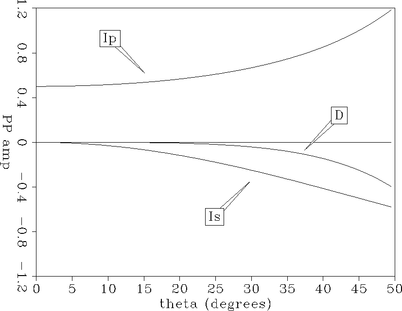
(Figure ![[*]](http://sepwww.stanford.edu/latex2html/cross_ref_motif.gif) ) which are based on linearized Zoeppritz equations.
) which are based on linearized Zoeppritz equations.
imped
Figure 11 Theoretical P, S and density
impedance inversion curves.

For a unit perturbation in relative P impedance contrast, the P impedance
inversion curve dominates at small angles of incidence and increases with
increasing angles of incidence. For a unit perturbation in relative S
impedance contrast, the S impedance inversion curve is zero at normal
incidence, and is increasingly negative with increasing offset. Over the
conventional range of surface reflection data acquisition
geometry illumination,
which is typically 0 to 35, the density inversion curve is not
significant, as most of the density contrast contributes to the reflection AVO
through the impedance contrasts alone.
As the reflection amplitudes are mostly a combination of the P and S impedance
contrast inversion curves, reflectors with P and S impedance contrasts of the
same polarity and magnitude are expected to show approximately constant
amplitudes versus offset. On the other hand, reflectors with P and S impedance
contrasts of opposite polarities, indicating a transition zone of changing rock
pore fluid properties, should show either increasing positive or increasing
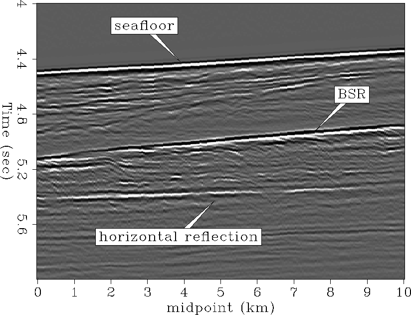
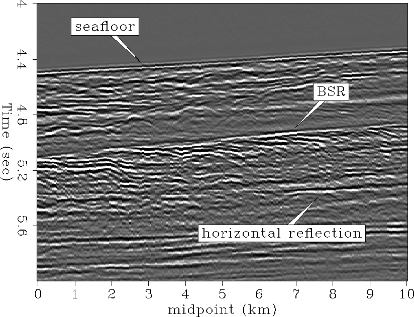
negative amplitude versus offset. The least-squares impedance inversion results of the preprocessed CMP gathers
are shown in Figures ![[*]](http://sepwww.stanford.edu/latex2html/cross_ref_motif.gif) and
and ![[*]](http://sepwww.stanford.edu/latex2html/cross_ref_motif.gif) .
.
pmp-ann
Figure 12 P impedance contrast


 smp-ann
Figure 13 S impedance contrast


Next: RESULTS
Up: PROCESSING STEPS
Previous: Preprocessing and velocity analysis
Stanford Exploration Project
11/16/1997
![[*]](http://sepwww.stanford.edu/latex2html/cross_ref_motif.gif) ) which are based on linearized Zoeppritz equations.
) which are based on linearized Zoeppritz equations.
![[*]](http://sepwww.stanford.edu/latex2html/cross_ref_motif.gif) ) which are based on linearized Zoeppritz equations.
) which are based on linearized Zoeppritz equations.

![[*]](http://sepwww.stanford.edu/latex2html/cross_ref_motif.gif) and
and ![[*]](http://sepwww.stanford.edu/latex2html/cross_ref_motif.gif) .
.

