

Next: Extending cross-line offset range
Up: Vaillant & Biondi: Extending
Previous: Introduction
One way to reduce the computational cost of 3-D prestack depth migration is to use common-azimuth data, which is only a 4-D dataset. Common-azimuth migration is then derived as the solution of the one-way wave equation through a recursive downward-continuation operator. In the frequency-wavenumber domain, this operator can be expressed as a simple phase-shift applied to the wavefield. We use the notation indicated below. The vertical wavenumber kz is given by a 3-D dispersion relation called the Double Square Root (DSR) equation Claerbout (1984):
| ![\begin{eqnarray}
DSR (\omega, \bold k_m, \bold k_h, z) = & \sqrt{\frac{\omega^2}...
...- \frac{1}{4} \left[ (k_{mx}-k_{hx})^2+(k_{my}-k_{hy})^2 \right] }\end{eqnarray}](img1.gif) |
|
| (1) |
where  is the midpoint wavenumber (
 ),
),  the offset wavenumber (
 ) and kz the vertical wavenumber (
 ), with
  ,
,  ,
,  and
and  unit vectors of the four midpoint and offset axes. The propagation velocities
  and
and  correspond respectively to the receiver and source locations.
The first square root in equation (1) downward-continues the receiver wavefield, whereas the second one downward-continues the source wavefield. In the algorithm developed by Biondi and Palacharla 1996, the data at the new depth level Dz+dz are obtained from common-azimuth data Dz by the following integration:
|  |
|
| (2) |
| |
In practice, we use the stationary-phase approximation to compute this integral (see Appendix A). Popovici 1995 finds a very similar expression for the kernel of migration to zero-offset (MZO) in 2-D and asserts that the stationary-phase approximation avoids the very high computational cost of a numerical evaluation of the integral.
In our case, the stationary phase approximation of the common-azimuth downward-continuation operator for data where hy=0 can be written as
|  |
(3) |
with the phase  .
.
For data evaluated only at the origin of the cross-line offset axis (hy=0), Biondi and Palacharla 1996 derived an analytical expression for the stationary point:
|  |
(4) |
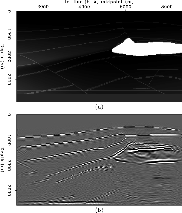
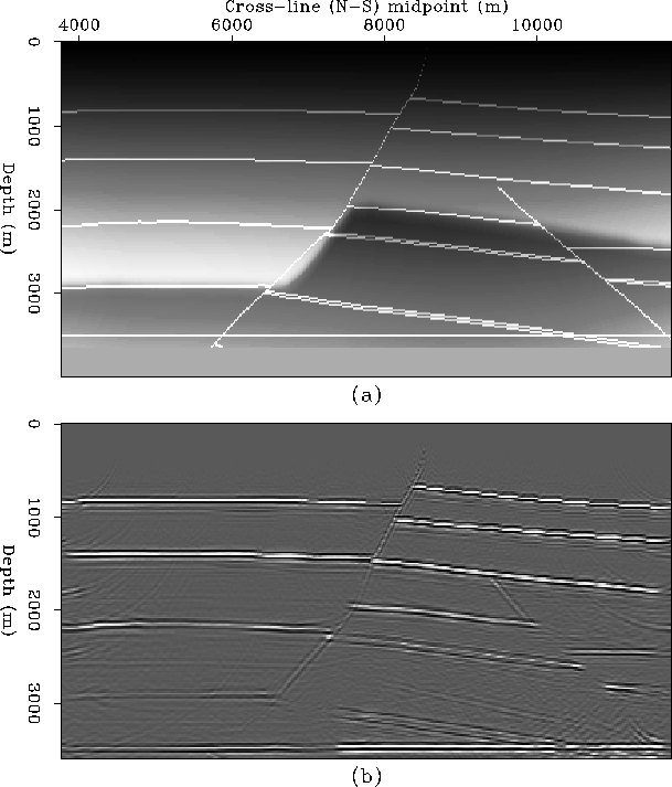
We have implemented the kernel of downward-continuation and phase-shift migration with the preceding theory. Simulations performed with the standard common-azimuth migration code have already proven its efficiency in imaging complex media Biondi (1999). As shown in Figures 1 and 2, the common-azimuth technique provides accurate subsalt images. Still, on the left side of Figure 1(b), imaging the major fault has obviously met with some difficulties, which can be attributed to rapid lateral variations of the velocity model. As seen in Figures 2(a) and 2(b), the same fault, now on the right side, is also dipping in the cross-line direction. Extending the common-azimuth technique may help improve the imaging of these lateral velocity variations.
SEG-EAGE-in
Figure 1 Common-azimuth prestack depth migration of data from the SEG-EAGE salt model. In-line section at CMPy=10400 (m). The top plot (a) represents the exact velocity model and the bottom plot (b) represents the migration result.


 SEG-EAGE-cross
Figure 2 Common-azimuth prestack depth migration of data from the SEG-EAGE salt model. Cross-line section at CMPx=2100 (m). The top plot (a) represents the exact velocity model and the bottom plot (b) represents the migration result.


Next: Extending cross-line offset range
Up: Vaillant & Biondi: Extending
Previous: Introduction
Stanford Exploration Project
4/20/1999
![\begin{eqnarray}
DSR (\omega, \bold k_m, \bold k_h, z) = & \sqrt{\frac{\omega^2}...
...- \frac{1}{4} \left[ (k_{mx}-k_{hx})^2+(k_{my}-k_{hy})^2 \right] }\end{eqnarray}](img1.gif)
![\begin{eqnarray}
DSR (\omega, \bold k_m, \bold k_h, z) = & \sqrt{\frac{\omega^2}...
...- \frac{1}{4} \left[ (k_{mx}-k_{hx})^2+(k_{my}-k_{hy})^2 \right] }\end{eqnarray}](img1.gif)


