Next: conclusions
Up: results
Previous: results
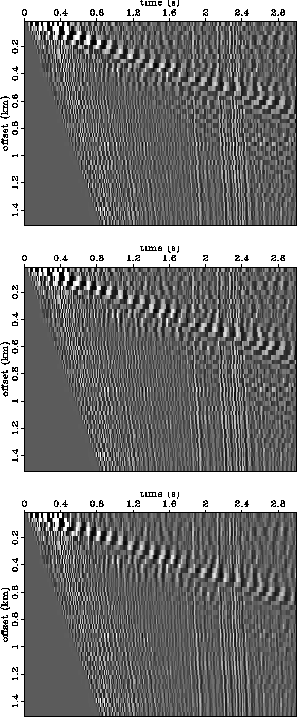
Ground roll is nearly always spatially aliased, so the relatively unaliased example of Figure 3
is a somewhat unrealistic exception to the practical rule. To inject some realism, we decimated the
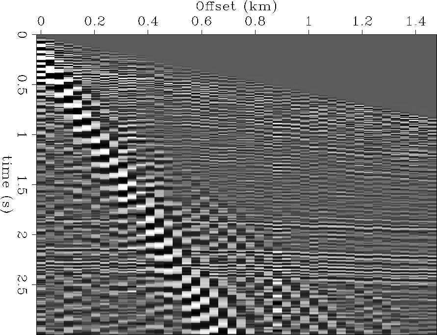
original 2-D shot gather (Figure 3) by a factor of two in offset, as shown in Figure
8, so that the ground roll is quite aliased. Figure 9
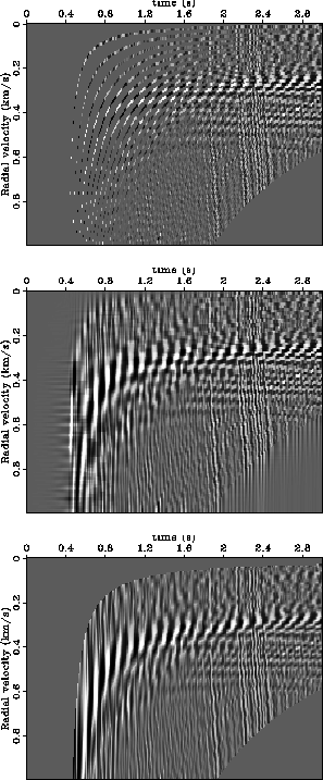
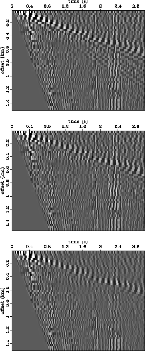
compares the RTT of the decimated data. The results are disappointing. Looking at the v-interpolation
without infill panel (top), the human eye can easily interpolate vertically to reconstruct the radial
events in RT space. Unfortunately, the v-interpolation panel with infill does not have the desired
vertical coherence. In fact, it would seem that the central premise motivating this paper -- that the
RTT maps ground roll to zero temporal frequency -- is violated.
Figures 10 and 11 are
analogous to Figures 6 and 7 --
they are the estimates of signal and noise, respectively. All implementations (v-interpolation with and
without infill, and x-interpolation) do an relatively poor job of noise suppression.
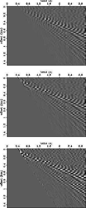
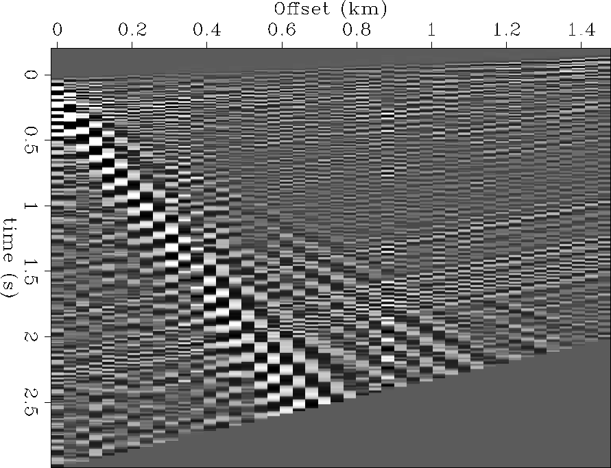
A simple way to dealias linear ground roll is to apply a linear moveout (LMO) correction. Figure
12 shows the result of applying a 1.5 km/sec LMO correction to the decimated data of
Figure 8. The ground roll is no longer spatially aliased, but the
primaries are also no longer ``flat'', as they were originally. As a result, interpolation errors for
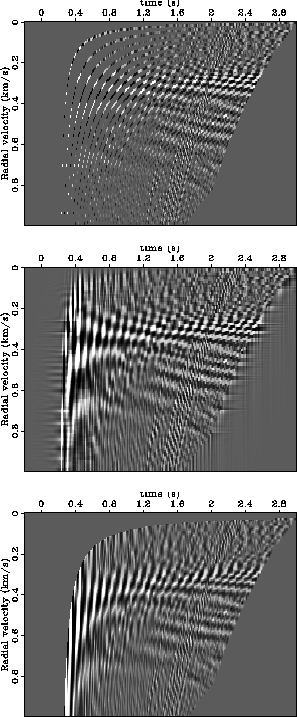
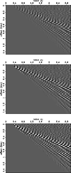
the x-interpolation RTT will increase. Figure 13 compares the RTT panels
for the decimated/LMO'ed data. The ground roll now occupies a higher effective velocity band,
and more importantly, is much closer to zero temporal frequency than in Figure 9.
The noise suppression achieved (Figure 14) is better than the case in which
LMO was not used (Figure 10). As expected, and mentioned above, the x-interpolation
RTT leads to severe losses of signal energy, quite a bit more severe than either of the two v-interpolation
implementations, as can be seen in Figure 15.
Unfortunately, both v-interpolation implementations seem to suffer some small signal losses, which suggests
that LMO may actually be ``aliasing'' the primaries by mapping them to low temporal frequency in the RT domain.
hectoralias-dat
Figure 8 Same 2-D shot gather as Figure 3,
only decimated by a factor of two in offset.
|
|  |


 hectoralias-radial-comp
Figure 9 Top: v-interpolation without infill.
Middle: v-interpolation with infill. Bottom: x-interpolation.
![[*]](http://sepwww.stanford.edu/latex2html/movie.gif)
hectoralias-estsig
Figure 10 Estimated signal.
Top: v-interpolation without infill.
Middle: v-interpolation with infill.
Bottom: x-interpolation.
hectoralias-estnoiz
Figure 11 Estimated noise.
Panels defined as in Figure 10.
hectorlmo-dat
Figure 12 Decimated 2-D shot gather (Figure
8), after 1.0 km/sec linear moveout correction.
|
|  |
hectorlmo-radial-comp
Figure 13 Top: v-interpolation without infill.
Middle: v-interpolation with infill. Bottom: x-interpolation.
hectorlmo-lmo-estsig
Figure 14 Estimated signal.
Top: v-interpolation without infill.
Middle: v-interpolation with infill.
Bottom: x-interpolation.
hectorlmo-lmo-estnoiz
Figure 15 Estimated noise.
Panels defined as in Figure 14.
Next: conclusions
Up: results
Previous: results
Stanford Exploration Project
4/28/2000