 |
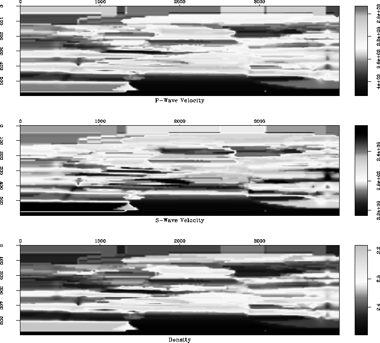
Figure 6 Brine-saturated section.
In order to study the effects of different fluids on AVO response, a suitable body in the diagram needed to be located which would show significant rock property change with a change in fluid Mavko and Mukerji (1995). Specifically, a body with high porosity would be the best choice. In Figure 5a there is a prominent feature in the center of the section at a depth of 100 meters, a thickness of 50 meters, and a width of around a kilometer. This body is interpreted as one of the many channel deposits present within the Stanford V dataset. The facies of this body is a relatively porous sand, with an associated low density, P-wave velocity, and S-wave velocity. The wide lateral extent, horizontal boundary, and sharp impedance contrast at both the top and base provide for good modeling because data can be looked at over a range of horizontal distance, and the amplitudes should be relatively strong Yilmaz (1987).
 |
The inputs needed to do the fluid substitution are the P-wave velocity, S-wave velocity, density, and porosity. Since the kriging uses spatial coordinates, and each of these variables is known at well locations, the same kriging parameters are used for the other variables as was used for the P-wave velocity kriging. This ensures that the rock properties of the sand body are relative throughout. S-wave velocities were given for only one horizontal well. Since S-wave velocities were needed in the whole section equation (4) was used to calculate Vs from Vp using knowledge of facies.
The facies in the Stanford V dataset are ranked from 0-3, with lower numbers associated with slower, more porous facies. Using knowledge of the facies at each point, and the Castagna relation,
| |
(4) |
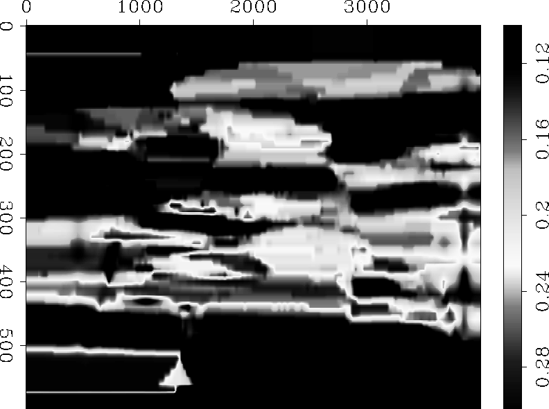
with the correct coefficients ai2, ai1, and ai2 (refer to Appendix), a value for Vs was assigned to each point Mavko (2000). So on each variable section, including Vs, the sand body is a very prominent feature. From the porosity section in Figure 7, it is seem than in fact there is a high porosity anomaly associated with this channel sand.
 |
The original data is assumed to be saturated with a brine fluid.
Values for Vp, Vs, and density of the brine saturated section (original data) are seen in Figure 6.
Because this body is different than the
surrounding rocks, the fluid substitution is easily implemented by simple scanning for anomalously
low P-wave velocities in that area, and doing the fluid substitution at these points.
The substitution requires units of K, bulk modulus, and ![]() shear modulus. Conversion using the
kriged sections requires a calculation at each point,
shear modulus. Conversion using the
kriged sections requires a calculation at each point,
| |
(5) |
| |
(6) |
The substitution is done using the Gassmann's Relations obtained from Mavko (2000)
(Equations 5 and 6). One Gassmann
assumption is that the shear modulus, ![]() , is the same for a dry and fluid saturated rocks. This is a safe
assumption since
, is the same for a dry and fluid saturated rocks. This is a safe
assumption since ![]() for fluids and gases is zero. The transform from brine saturated to dry is as follows:
for fluids and gases is zero. The transform from brine saturated to dry is as follows:
 |
(7) |
where K is the Bulk modulus ![]() is the porosity. The mineral is assumed to be quartz, with K=36.6 Gpa. With
this Kdry, the Ksat for and fluid can be found using the following relation:
is the porosity. The mineral is assumed to be quartz, with K=36.6 Gpa. With
this Kdry, the Ksat for and fluid can be found using the following relation:
 |
(8) |
where the Kmin is again assumed to be 36.6 Gpa for quartz Mavko (2000).
Using this algorithm, the sand body was substituted with both
oil (K=0.5 Gpa, ![]() =0.6 g/cm3) and gas (K=0.03 Gpa,
=0.6 g/cm3) and gas (K=0.03 Gpa, ![]() =.116 g/cm3). The plots of Vp, Vs, and density are shown in
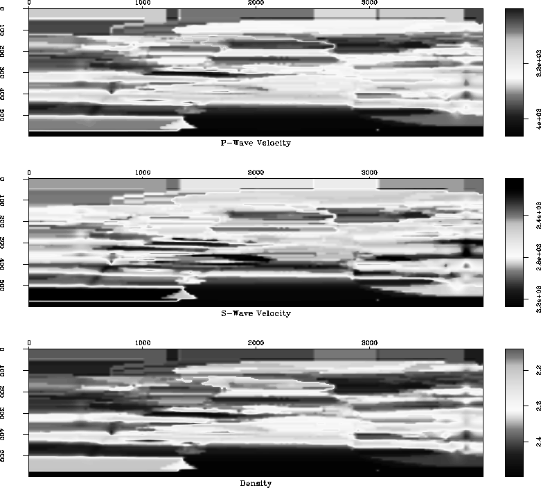
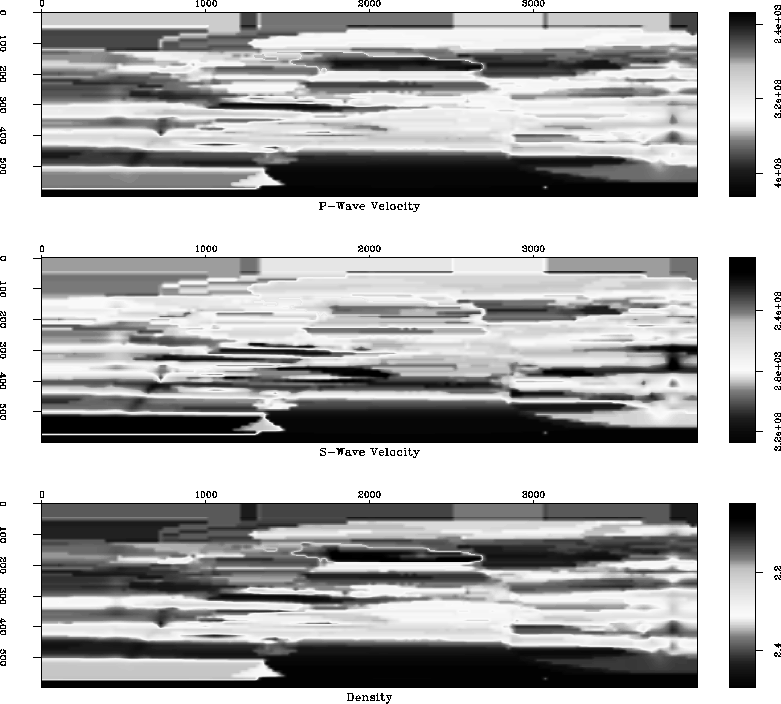
Figure 8 and Figure 9 for oil and gas substitution, respectively.
As expected, the substitution of oil and gas decrease Vp because
these fluids are not as stiff as brine. The densities go down as well, and this causes an increase in Vs, because
=.116 g/cm3). The plots of Vp, Vs, and density are shown in
Figure 8 and Figure 9 for oil and gas substitution, respectively.
As expected, the substitution of oil and gas decrease Vp because
these fluids are not as stiff as brine. The densities go down as well, and this causes an increase in Vs, because
![]() stays the same.
stays the same.
 |
 |