Next: LIMITATIONS
Up: Van Trier & Symes:
Previous: Initial and boundary conditions
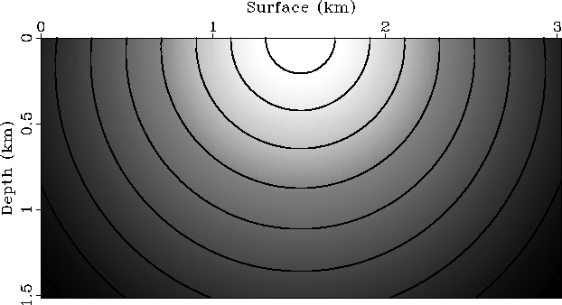
In the first example we calculate traveltimes for a medium
with a velocity gradient linear with respect
to depth (the constant-velocity case is trivial in polar coordinates).
The velocity at the top of the model is 2 km/s, the one at the bottom
2.5 km/s.
The grid is evenly sampled in
depth and laterally, with a sample interval of 10 m. Figure 2
shows the traveltime function for a source on
the surface at the middle of the model, and Figure 3
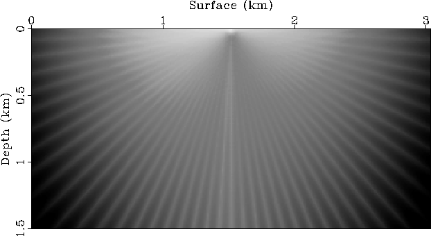
displays the difference between that function and the analytical solution.
Finite-difference traveltimes are calculated in polar coordinates, and errors
accumulate as the radius increases. A simple bilinear interpolation is
used in the mapping from and to Cartesian coordinates. Although
interpolation errors in that mapping are not large, they
cause the distinct pattern visible in Figure 3.
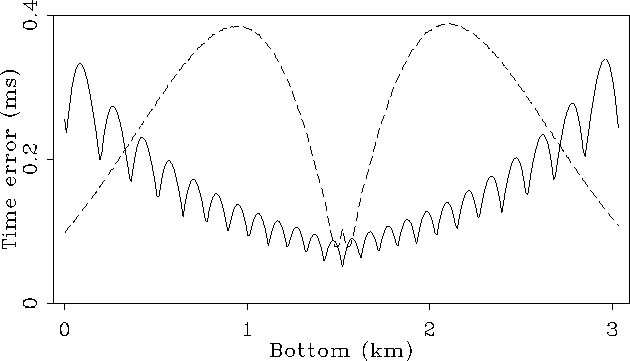
The maximum error is about .3 ms (see Figure 5),
which is one order of magnitude smaller than
the standard time-sampling interval of 4 ms.
fdtimelin
Figure 2 Finite-difference traveltime field
for a model with a velocity function that is linearly increasing as a function
of depth.
The source is located at the surface in the middle of the model.
The figure displays both an intensity and contour plot of the traveltime field.
Low intensities denote small traveltimes; contour lines are
drawn at .1 s intervals.
 difftime
Figure 3 Difference between the traveltime
map of Figure 2 and the analytical solution. Higher
intensities in the plot represent larger errors.
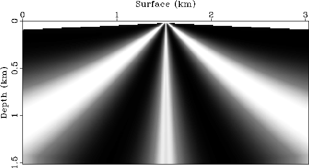
diffvidtime
Figure 4 Difference between a traveltime function
calculated with Vidale's plane-wave extrapolation method and the
analytical solution.
Figure 4 shows the difference between Vidale's scheme and
the analytical solution. We have implemented only the plane-wave
extrapolation method, and errors can probably be reduced
if a combination of plane and circular wave extrapolation is
used. The errors are largest away from the vertical, diagonal, and horizontal
directions, where the plane-wave approximation breaks down.
The errors at the bottom of the model are of the same magnitude
as the errors in the method described here (again see Figure 5).
bottom
Figure 5 Errors in the finite-difference
traveltime calculations at the bottom of model. The solid line
represents the error curve for the method described here, the dashed line
denotes the errors in Vidale's scheme.
strmodbnd
Figure 6 Wedge model. The grid
spacing is  m. Low intensities denote low velocities.
The interfaces between the
different layers are represented by solid lines in the figure.
The dashed line denotes an imaginary reflector in the
bottom layer. Figure 10 shows reflection events that correspond
to these reflectors.
m. Low intensities denote low velocities.
The interfaces between the
different layers are represented by solid lines in the figure.
The dashed line denotes an imaginary reflector in the
bottom layer. Figure 10 shows reflection events that correspond
to these reflectors.
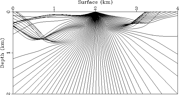
raystr
Figure 7 Rays traced through a smoothed version
of the model in Figure 6.
The next example illustrates the calculations for a more complicated model.
The model is shown in Figure 6; it consists of 3 layers and a
wedge intrusion. The velocity in the top layer is
2 km/s, the middle layer has a velocity of 1.75 km/s, and the bottom layer's
velocity is 2.5 km/s. The velocity in the wedge that intrudes the
middle layer from the right is 2.75 km/s.
Figure 7 shows
the result of tracing rays through a smoothed version of the model.
The smoothing causes the rays to bend or turn in
regions with a large velocity gradient.
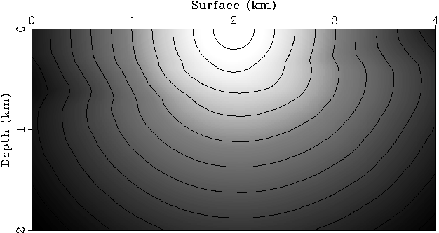
fdtimestr
Figure 8 Finite-difference traveltimes
calculated for the model of Figure 6. Overlain on the
figure are contour lines of the traveltime field. The contour interval
is .1 s.
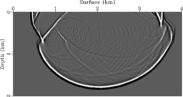
wave
Figure 9 Comparison of the wave field computed by
wave-equation modeling with the traveltime field calculated by
upwind finite-differences. The intensity plot shows a snapshot of
the wave field at .7s; the overlain dashed curve is the .7s-contour of the
traveltime function (see Figure 8).
As is obvious from Figure 7,
interpolating traveltimes from the rays onto the grid is not easy
for this model; some parts of the model are not illuminated by rays, and in
some other parts rays cross. However, the finite-difference
calculation correctly fills
in the problem areas as can be seen in Figure 8:
the contour lines in the plot reveal the correct curvature of the wave fronts
in the high- and low-velocity regions.
This result is verified in Figure 9, which shows
the result of finite-difference wave-equation modeling.
The figure displays a
snapshot of the wave field at .7 s. Also shown in the figure is
the .7s-contour line of the traveltime function (Figure 8).
Barring some discrepancies due to
the limited bandwidth and dispersion of the source wavelet,
the contour exactly follows the first-arrival
wave front. In particular note the match between wave field and
traveltime function in the upper-right corner of the model,
where the refracted wave travels in front of the direct wave.
Next: LIMITATIONS
Up: Van Trier & Symes:
Previous: Initial and boundary conditions
Stanford Exploration Project
1/13/1998