


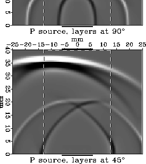
![[*]](http://sepwww.stanford.edu/latex2html/cross_ref_motif.gif) shows the situation for P waves for two different core layering
orientations in Vernik and Nur's experiment.
shows the situation for P waves for two different core layering
orientations in Vernik and Nur's experiment.
In the upper plot the layers run vertically; there is no tendency for the wave energy to ``slip sideways'' and the flat part of the wavefront impacts the receiver transducer well centered. We can see from the figure that things are working correctly in this case. Mathematically this is because the group and phase velocities happen to be the same for this propagation direction. The same good behavior also occurs when the layers in the core run horizontally, because this also sends the waves along a symmetry direction where the group and phase velocities are identical (for all wavetypes).
The situation is not so happy in the lower plot. Here the layers are
at a ![]() angle, running from the lower right to the upper left.
The P wave travels faster along the layers than across them; as a result
the ``flat'' part of the wavefront (containing the main focus of energy)
tends to follow the layers and slips sideways to the left. In our particular
example the accumulated sideways slip from bottom to top happens to be about
the same as the transducer widths,
so the ``flat'' part of the wavefront only just grazes the edge
of the receiver.
What traveltime will be measured in this case?
angle, running from the lower right to the upper left.
The P wave travels faster along the layers than across them; as a result
the ``flat'' part of the wavefront (containing the main focus of energy)
tends to follow the layers and slips sideways to the left. In our particular
example the accumulated sideways slip from bottom to top happens to be about
the same as the transducer widths,
so the ``flat'' part of the wavefront only just grazes the edge
of the receiver.
What traveltime will be measured in this case?
 |

 |
)
would change as a function of two normally fixed parameters,
source-receiver transducer offset (left subplot) and
source and receiver transducer width (right subplot).
In the ``real life'' case the transducer offset
was fixed at mm and the transducer width was fixed at 12mm.
In the left subplot the transducer width is held at 12mm, but
the transducer offset is allowed to vary from -24mm to +12mm
(with individual wiggle traces shown every 6mm).
In the right subplot the transducer offset is held at mm,
but the transducer width is allowed to vary by 4mm steps
from mm to 16mm (and then is abruptly jumped to
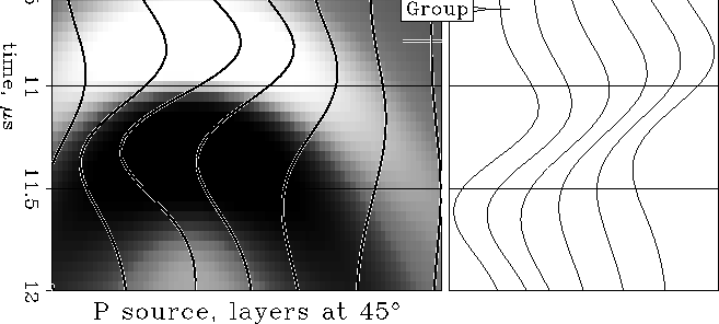
The answer is contained in Figure .
The left part of this figure shows the result of a tiny ``seismic survey''
over the shale-core model. The source transducer is held fixed.
The horizontal axis shows how the trace recorded at the receiver
would vary with offset if the receiver were moved around
(instead of glued in place).
The first break on the earliest arrival
occurs at 10.29![]() s for an offset of -12mm.
(The ``correct'' phase-velocity arrival time as
defined by running the model with infinite-length transducers
is very slightly later, 10.30
s for an offset of -12mm.
(The ``correct'' phase-velocity arrival time as
defined by running the model with infinite-length transducers
is very slightly later, 10.30![]() s. We will remark further
on this in the discussion.)
The first break at zero offset (and thus what corresponds
to the signal recorded in the actual experiment)
occurs at 10.34
s. We will remark further
on this in the discussion.)
The first break at zero offset (and thus what corresponds
to the signal recorded in the actual experiment)
occurs at 10.34![]() s. If this time were used to
calculate the vertical phase velocity it would cause an error
of only
s. If this time were used to
calculate the vertical phase velocity it would cause an error
of only ![]() , which is smaller than the typical errors Vernik and Nur
encountered in picking first breaks in their experiment,
about
, which is smaller than the typical errors Vernik and Nur
encountered in picking first breaks in their experiment,
about ![]() for P waves and
for P waves and ![]() for S waves.
(The only significant effect of the borderline miss in our simulated experiment
is a
for S waves.
(The only significant effect of the borderline miss in our simulated experiment
is a ![]() drop in trace amplitude.)
drop in trace amplitude.)
| offset (mm) | break | % delay | peak | % delay | % amplitude |
| -12 (peak) | 10.29 | 10.79 | 100 | ||
| -6 | 10.30 | .1 | 10.82 | .3 | 85 |
| 0 (actual) | 10.34 | .5 | 10.94 | 1.5 | 52 |
| 6 | 10.48 | 1.8 | 11.17 | 3.7 | 29 |
| 12 | 10.78 | 4.8 | 11.52 | 7.1 | 16 |
| transducer size (mm) | break | % delay | peak | % delay | |
| 10.30 | 10.84 | ||||
| 24 | 10.30 | .0 | 10.84 | .0 | |
| 20 | 10.30 | .0 | 10.85 | .1 | |
| 16 | 10.31 | .1 | 10.88 | .4 | |
| 12 (actual) | 10.34 | .3 | 10.94 | .9 | |
| 8 | 10.42 | 1.2 | 11.02 | 1.7 | |
| 4 | 10.54 | 2.3 | 11.08 | 2.2 | |
| 0 (group) | 10.63 | 3.2 | 11.10 | 2.4 |
Table 1 shows how the first-break time varied with offset for the traces
shown in the left part of Figure .
From the table we can discern that
if the miss had been smaller
(say if the anisotropy had been less, the transducers had been wider,
or the core had been shorter),
there would have been an insignificant delay in the first break and
only a very small drop in amplitude.
If the miss had been by more, on the other hand
(say if the anisotropy had been slightly greater, the transducers had been
narrower, or the core had been taller),
the first break would have been significantly delayed.
Essentially, if any of the leading ``flat part'' of the wavefront manages to
hit the receiver it is enough to initiate a first break at the true
phase-velocity arrival time; if the flat part misses completely
the error can be substantial.
The right part of Figure demonstrates this another way, by
showing the results of re-running the numerical experiment
for a range of transducer sizes. Zero-offset traces corresponding
to what would be measured by a laboratory experiment are shown.
With a point source and point receiver, the first break measures
the group-velocity arrival time, 10.63![]() s. As the transducer size is
increased towards 12mm the first break moves rapidly earlier to within
s. As the transducer size is
increased towards 12mm the first break moves rapidly earlier to within
![]() of the phase-velocity arrival time. As the transducer size is
increased yet further the first-break time closes in on the phase-velocity
arrival time more slowly, finally reaching it when the transducer width
is 20mm. All wider transducers measure the phase-velocity arrival time.
(Table 2 gives the numbers for this case.)
of the phase-velocity arrival time. As the transducer size is
increased yet further the first-break time closes in on the phase-velocity
arrival time more slowly, finally reaching it when the transducer width
is 20mm. All wider transducers measure the phase-velocity arrival time.
(Table 2 gives the numbers for this case.)