|
loray
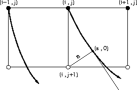
Figure 2 Local paraxial wavefront extrapolation. |  |
As in the case of the finite difference method, the description of the computational scheme of the local paraxial ray method consists of two parts. The first part addresses the local computation that determines how the traveltime and amplitude at a point are computed from the traveltimes and amplitudes at its neighbors. The second part explains the order in which the local computation proceeds. This note focuses on the description of the principles of the local computation. It should not be difficult to adapt these principles to the propagation schemes developed by Vidale and others.
|
loray
Figure 2 Local paraxial wavefront extrapolation. |  |
The local computational scheme of the local paraxial ray method can be divided
into two steps. As shown in Figure ![[*]](http://sepwww.stanford.edu/latex2html/cross_ref_motif.gif) , we assume that we know
the traveltimes, the ray directions, the second-order partial derivatives
of the traveltimes with respect to n, and the values of the Jacobian function
at the grid points marked with dots, and we want to compute these quantities
at the grid points marked with circles. The first step is to trace rays locally
from every grid point marked with a dot and to compute traveltime
, we assume that we know
the traveltimes, the ray directions, the second-order partial derivatives
of the traveltimes with respect to n, and the values of the Jacobian function
at the grid points marked with dots, and we want to compute these quantities
at the grid points marked with circles. The first step is to trace rays locally
from every grid point marked with a dot and to compute traveltime ![]() ,
function M(s,0), and Jacobian J(s,0) along each ray. To do so,
we need to solve the ray equation and equation (3), and
perform the integrations in equations (1) and (2).
The second step interpolates these quantities computed along the rays onto
the grid points marked with circles. Let us take grid point (i,j+1)
as an example. As indicated in Figure
,
function M(s,0), and Jacobian J(s,0) along each ray. To do so,
we need to solve the ray equation and equation (3), and
perform the integrations in equations (1) and (2).
The second step interpolates these quantities computed along the rays onto
the grid points marked with circles. Let us take grid point (i,j+1)
as an example. As indicated in Figure ![[*]](http://sepwww.stanford.edu/latex2html/cross_ref_motif.gif) , we can find
ray-centered coordinates (s,n) of this point that are associated with the ray
traced from grid point (i,j). If we assume that the grid sizes are
small enough that the paraxial approximation is always valid,
then we can use equation (4)
to find the traveltime at grid point (i,j+1) and use
equation (7) to compute the value of the Jacobian function
that is related to the amplitude at this point. Two other quantities are
required in order to continue the local ray tracing from the grid point
(i,j+1). One is the ray direction at this point. The ray direction
can be determined from the gradient of the traveltime that can
be computed from equation (5).
The other quantity is the value of function M(s,n), which
serves as the initial condition of the dynamic ray tracing equation at this
point and can be computed from equation (6).
If possible, we do the same computation
for each ray passing by point (i,j+1) and pick the result that is associated
with the minimum traveltime. This completes the local computation.
, we can find
ray-centered coordinates (s,n) of this point that are associated with the ray
traced from grid point (i,j). If we assume that the grid sizes are
small enough that the paraxial approximation is always valid,
then we can use equation (4)
to find the traveltime at grid point (i,j+1) and use
equation (7) to compute the value of the Jacobian function
that is related to the amplitude at this point. Two other quantities are
required in order to continue the local ray tracing from the grid point
(i,j+1). One is the ray direction at this point. The ray direction
can be determined from the gradient of the traveltime that can
be computed from equation (5).
The other quantity is the value of function M(s,n), which
serves as the initial condition of the dynamic ray tracing equation at this
point and can be computed from equation (6).
If possible, we do the same computation
for each ray passing by point (i,j+1) and pick the result that is associated
with the minimum traveltime. This completes the local computation.