

Next: SUMMARY
Up: DEFINING AN IMAGING CRITERION
Previous: The V-stack criterion
The relevance of obtaining an estimation of the several angle-dependent
reflection coefficients is the prospect of later using these information
in a Zoeppritz-based elastic inversion. However, since the Zoeppritz
equations represent the plane-wave response of a planar interface,
it is necessary that the reflectivity estimation also represent
the in situ plane-wave response of the interface.
From the previous criteria, only the V-stack represents a reasonable
approximation to this requirement. To obtain an estimation completely
consistent with the plane-wave response it necessary to perform a
complete plane-wave decomposition of the upward and downward propagating
wavefields at each point of the model, for all time steps. Although
this criterion can be applied to general RTM schemes, it is particularly
appropriate for the one-experiment approach described in
Cunha (1992), where a single wavefield (with combined information
form the modeled and recorded wavefields) is backward propagated
in time using a discontinuous background model.
The implementation of the plane-wave decomposition criterion for the
one-experiment RTM scheme is outlined below
-
First, it is necessary to separate the downgoing
 and
upcoming
  components of the wavefield potential, using
the propagation-direction unit vector
  Appendix A describes how to obtain the propagation direction
from the field potentials. The downgoing field (within the forward time
reference system) includes the incident and the transmitted wavefields,
while the upcoming field contains only the reflections
Appendix A describes how to obtain the propagation direction
from the field potentials. The downgoing field (within the forward time
reference system) includes the incident and the transmitted wavefields,
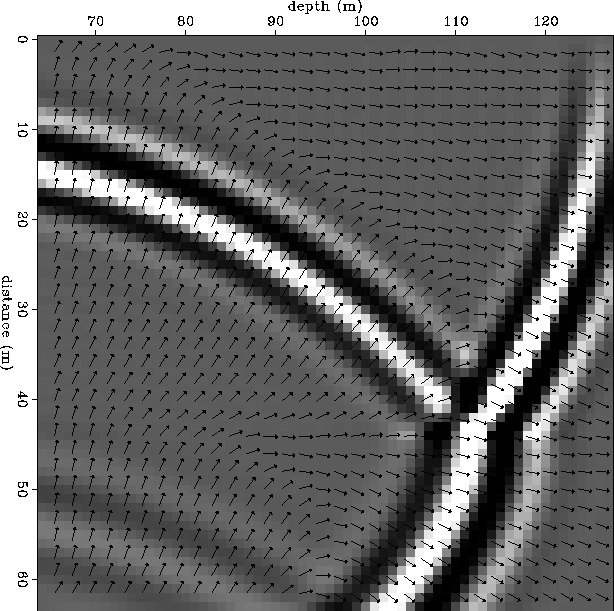
while the upcoming field contains only the reflections![[*]](http://sepwww.stanford.edu/latex2html/foot_motif.gif) . Figure
. Figure ![[*]](http://sepwww.stanford.edu/latex2html/cross_ref_motif.gif) shows the
estimated propagation directions overlain on the wavefield and
Figure
shows the
estimated propagation directions overlain on the wavefield and
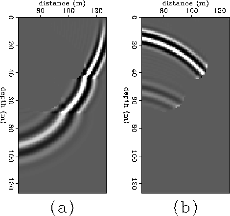
Figure ![[*]](http://sepwww.stanford.edu/latex2html/cross_ref_motif.gif) shows the resulting upcoming and downgoing
separated wavefields.
shows the resulting upcoming and downgoing
separated wavefields.
-
The second step involves the computation of the stacking power of
the two wavefields (
 and
and  ) along the directions
represented by the angle
  around each point of the model
As in the V-stack case, the stacking power here is computed outward
from the image point (stacking trajectories are like a clock's hand),
instead of across it. This implies that
 . As discussed in appendix B
the point of a given interface that intersects the downgoing wavefield
at time t (reflection point) will have two directions
  (almost
opposite) for which the
  has a local maximum, corresponding
to the incident and transmitted waves, but only one direction for
which the
  is maximum.
wdir
Figure 7 Wavefield partition at an interface. The incident and transmitted wavefields
propagate downward while the reflected wavefield propagates upward. The
overlaid arrows indicate the local propagation direction estimated from
the wavefield as described in appendix A.


 wavesep
Figure 8 Separation of the upward-propagating and downward-propagating parts of
a wavefield using the local propagation direction. (a) The downward-propagating
part corresponding to the incident and transmitted wavefields. (b) The
upward-propagating part corresponding to the reflected wavefields.

-
Evaluate the angle
 for which
  is maximum. For
reasons discussed in appendix B this angle determines
the subdomain
  in which the correlation
between the two stacking power functions is to be evaluated.
-
Next, the crosscorrelation
 of the two stacking powers, and
the autocorrelation
  of the stacking power of the downgoing
wavefield are evaluated, in the interval
  for points
  where
where  and
for points
  where
where  where
where  is the reflection angle.
-
The estimated attribute is given by
|  |
|
| (12) |
where

mig1time
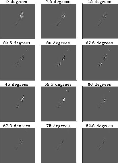
Figure 9 PP reflectivity for a small (6 time steps) time window of the wavefield
in Figure ![[*]](http://sepwww.stanford.edu/latex2html/cross_ref_motif.gif) , for different values of the angle of incidence
, for different values of the angle of incidence
 .
.

Figure ![[*]](http://sepwww.stanford.edu/latex2html/cross_ref_motif.gif) shows the twelve images obtained over a small time
window centered at the time-frame of Figure
shows the twelve images obtained over a small time
window centered at the time-frame of Figure ![[*]](http://sepwww.stanford.edu/latex2html/cross_ref_motif.gif) . Each of these
images correspond to
. Each of these
images correspond to  at a different local angle of
incidence
  . The ray-theoretical values for the angle of incidence
of the wavefronts that reach the two interfaces at that particular time
are: 48 degrees for upper interface and 30.5 degrees for the bottom
interface. From the figure it is clear that the point of the
upper interface that is imaged at this time has maximum energy at
the frames corresponding to 45 and 52.5 degrees, while for
the bottom interface the maximum occurs at 30 and 37.5 degrees.
Though special care will be required to avoid the undesirable focusing
at small angles that we observe in the figure, it is encouraging to see
that the location of the main maxima are consistent with the expected values.


Next: SUMMARY
Up: DEFINING AN IMAGING CRITERION
Previous: The V-stack criterion
Stanford Exploration Project
11/18/1997
![[*]](http://sepwww.stanford.edu/latex2html/foot_motif.gif) . Figure
. Figure ![[*]](http://sepwww.stanford.edu/latex2html/cross_ref_motif.gif) shows the
estimated propagation directions overlain on the wavefield and
Figure
shows the
estimated propagation directions overlain on the wavefield and
Figure ![[*]](http://sepwww.stanford.edu/latex2html/cross_ref_motif.gif) shows the resulting upcoming and downgoing
separated wavefields.
shows the resulting upcoming and downgoing
separated wavefields.


![]()
