


The Dip Moveout correction (DMO) is in fact an extension to the NMO correction when dips are present. In the presence of only horizontal layers NMO tries to correct the effect of the offset and transform all the constant-offset section into zero-offset section. You can understand the DMO correction as doing exactly the same thing not only for horizontal events but also for dipping events. DMO is an intermediate processing step which attempts to position the conflicting dips in the correct zero-offset location such that after NMO, CMP stacking will not attenuate crossing events.
These concepts are all
formulated for a constant velocity medium.
For a variable velocity medium the transformation
from constant-offset to zero-offset performed by NMO
combined with DMO can not be split into two
separate processes; instead it forms a single step process
called Migration to Zero-Offset (MZO).
In constant
velocity media ![]() .
.
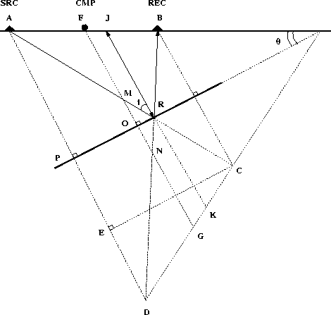
To define the parameters involved in the DMO correction
we need to analyze the kinematics of the constant-offset
reflection of a dipping layer.
For a horizontal layer, the reflection point is situated right
under the location of the common-midpoint (CMP). For the
dipping layer sketched in Figure ![[*]](http://sepwww.stanford.edu/latex2html/cross_ref_motif.gif) the reflection point for
the source-receiver ray is R.
This point is positioned updip relative to the intersection O of
the zero-offset ray from the common-midpoint F
with the dipping reflector.
the reflection point for
the source-receiver ray is R.
This point is positioned updip relative to the intersection O of
the zero-offset ray from the common-midpoint F
with the dipping reflector.
In a constant-offset section the trace corresponding
to a source positioned at point A and a receiver
positioned at point B is placed in the location
of the CMP. However in a zero-offset experiment
the reflection point R is observed from the surface position
J. Migration to zero-offset ![]() is the transformation which
relocates a reflection point as seen in constant-offset to
a place corresponding to the reflection point as seen in zero-offset.
is the transformation which
relocates a reflection point as seen in constant-offset to
a place corresponding to the reflection point as seen in zero-offset.
 |

In order to define the operator we have to calculate the time
correction and the surface coordinate correction to transform
a constant-offset section into a zero-offset section.
In Figure the segment JR represents the zero-offset
ray from the reflection point R. The segment FJ
represents the surface correction from the CMP
to the real zero-offset position of both the source and receiver.
We can calculate the surface correction and the traveltime
correction using some elementary geometry.
The source-receiver traveltime th corresponds to the ray path ARB. The velocity of the medium is v and the constant-offset traveltime is
![]()
![]()
From Figure we observe that the most important equation
relating the angle of the dipping reflector and the incidence angle
of the constant-offset raypath is
| |
(4) |
![]()
To calculate the segment ![]() which is the DMO surface
correction we note that
which is the DMO surface
correction we note that
![]()
![]()
| |
(5) |
| |
(6) |
Knowing segment FJ, the zero-offset traveltime given by the segment JK is calculated as
![]()
![]()
| |
(7) |
We have obtained the parametric equations defining the
![]() operator in constant velocity media:
operator in constant velocity media:
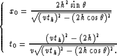 |
(8) |
The formulas in equation () tell us where
an event from a constant-offset section is moved in a
zero-offset section when the dip is known. However we will
see later that the dip doesn't have to be known to
correctly apply the DMO operator. Figure
shows the variation of t0 and x0 for a whole range of dips.
For a zero dip we have
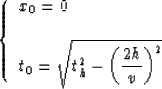
|
MZOimpulse
Figure 5 The distribution of the DMO correction for all dips | 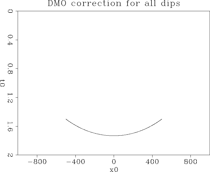 |