

Next: CONCLUSIONS
Up: Introduction
Previous: Remapping in
The function inside the integral in equation (13)
satisfies the partial differential equation
|  |
(15) |
Notice that for flat layers (pyy=0) the equation
is reduced to

which is solved by doing NMO as time migration
in time and offset coordinates. For the zero-offset case
(phh=0), the equation becomes an identity.
To verify the partial differential equation, I coded equation
(13) for a constant velocity case and for several
depth varying velocity functions.
Equation (13) can be used to extrapolate the
initial wavefield in t0 using a vrms velocity for each
zero-offset time value. The results are shown in the following
synthetic cases.
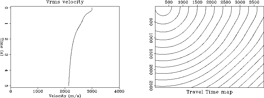
Figure ![[*]](http://sepwww.stanford.edu/latex2html/cross_ref_motif.gif) shows the velocity and the travel-time
map used to model the constant-offset sections. Since for this first
case the velocity was constant the information in this
figure is trivial, however I kept it just to be consistent
with the layout of the other figures. The number of
offsets used is 32, with a maximum half-offset h=930 meters.
In all cases the structural model was a diffractor at a depth of
1250 m.
Figure
shows the velocity and the travel-time
map used to model the constant-offset sections. Since for this first
case the velocity was constant the information in this
figure is trivial, however I kept it just to be consistent
with the layout of the other figures. The number of
offsets used is 32, with a maximum half-offset h=930 meters.
In all cases the structural model was a diffractor at a depth of
1250 m.
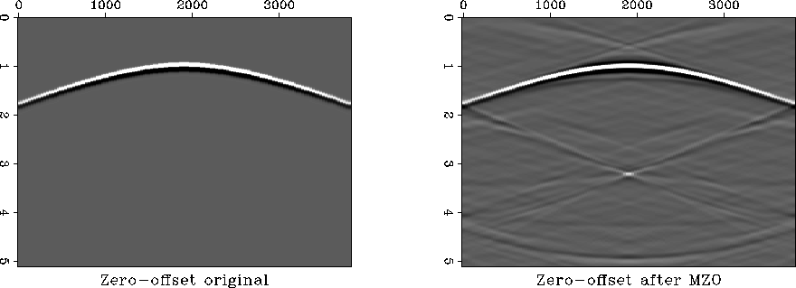
Figure ![[*]](http://sepwww.stanford.edu/latex2html/cross_ref_motif.gif) shows a comparison between the first zero-offset
panel obtained from modeling and the output of the MZO algorithm
applied to the 32 constant-offset sections.
The kinematics of the initial zero-offset section in Figure
shows a comparison between the first zero-offset
panel obtained from modeling and the output of the MZO algorithm
applied to the 32 constant-offset sections.
The kinematics of the initial zero-offset section in Figure
![[*]](http://sepwww.stanford.edu/latex2html/cross_ref_motif.gif) a coincide with the output of the MZO algorithm
in Figure
a coincide with the output of the MZO algorithm
in Figure ![[*]](http://sepwww.stanford.edu/latex2html/cross_ref_motif.gif) b. The artifacts in Figure
b. The artifacts in Figure ![[*]](http://sepwww.stanford.edu/latex2html/cross_ref_motif.gif) b are
due to the Fourier domain implementation of the algorithm.
The next figures use a depth variable velocity to model the
constant-offset sections and the corresponding vrms
to migrate the data to zero-offset.
b are
due to the Fourier domain implementation of the algorithm.
The next figures use a depth variable velocity to model the
constant-offset sections and the corresponding vrms
to migrate the data to zero-offset.
Figure ![[*]](http://sepwww.stanford.edu/latex2html/cross_ref_motif.gif) a shows a root-mean-square velocity with
a slow increase, corresponding to an interval velocity with
several linearly increasing velocity layers. The travel-time
map model in Figure
a shows a root-mean-square velocity with
a slow increase, corresponding to an interval velocity with
several linearly increasing velocity layers. The travel-time
map model in Figure ![[*]](http://sepwww.stanford.edu/latex2html/cross_ref_motif.gif) b can be used to identify the
boundaries of sharper velocity changes.
Comparing Figures
b can be used to identify the
boundaries of sharper velocity changes.
Comparing Figures ![[*]](http://sepwww.stanford.edu/latex2html/cross_ref_motif.gif) a and
a and ![[*]](http://sepwww.stanford.edu/latex2html/cross_ref_motif.gif) b we notice the
excellent kinematic match between the zero-offset model
and the output of the migration to zero-offset algorithm
using the depth variable velocity.
b we notice the
excellent kinematic match between the zero-offset model
and the output of the migration to zero-offset algorithm
using the depth variable velocity.
Figure ![[*]](http://sepwww.stanford.edu/latex2html/cross_ref_motif.gif) shows
a velocity model with an increasing jump, while in Figure
shows
a velocity model with an increasing jump, while in Figure ![[*]](http://sepwww.stanford.edu/latex2html/cross_ref_motif.gif) ,
the velocity has a decreasing jump. Again in both cases,
comparing Figures
,
the velocity has a decreasing jump. Again in both cases,
comparing Figures ![[*]](http://sepwww.stanford.edu/latex2html/cross_ref_motif.gif) a with
a with ![[*]](http://sepwww.stanford.edu/latex2html/cross_ref_motif.gif) b and Figures
b and Figures
![[*]](http://sepwww.stanford.edu/latex2html/cross_ref_motif.gif) a with
a with ![[*]](http://sepwww.stanford.edu/latex2html/cross_ref_motif.gif) b, the
kinematics of the initial zero-offset section and the
output of the migration to zero-offset are extremely similar
even though the velocities used show quite large variations.
b, the
kinematics of the initial zero-offset section and the
output of the migration to zero-offset are extremely similar
even though the velocities used show quite large variations.
Fig1
Figure 1 The constant velocity medium case.
a. Vrms velocity used.
b. Zero-offset travel-time map used for modeling.


 Fig2
Fig2
Figure 2 Comparison between zero-offset input and constant velocity
MZO output.
a. First panel in the input cube: zero-offset.
b. MZO output after stacking.


 Fig3
Fig3
Figure 3 The depth variable velocity case.
a. Vrms velocity used.
b. Zero-offset travel-time map used for modeling.


 Fig4
Fig4
Figure 4 Comparison between zero-offset input and v(z) velocity MZO output.
a. First panel in the input cube: zero-offset.
b. MZO output after stacking.


 Fig5
Fig5
Figure 5 The depth variable velocity case.
a. Vrms velocity used.
b. Zero-offset travel-time map used for modeling.


 Fig6
Fig6
Figure 6 Comparison between zero-offset input and v(z) velocity MZO output.
a. First panel in the input cube: zero-offset.
b. MZO output after stacking.


 Fig7
Fig7
Figure 7 The depth variable velocity case.
a. Vrms velocity used.
b. Zero-offset travel-time map used for modeling.


 Fig8
Fig8
Figure 8 Comparison between zero-offset input and v(z) velocity MZO output.
a. First panel in the input cube: zero-offset.
b. MZO output after stacking.


Next: CONCLUSIONS
Up: Introduction
Previous: Remapping in
Stanford Exploration Project
11/17/1997
![]()
![[*]](http://sepwww.stanford.edu/latex2html/cross_ref_motif.gif) shows the velocity and the travel-time
map used to model the constant-offset sections. Since for this first
case the velocity was constant the information in this
figure is trivial, however I kept it just to be consistent
with the layout of the other figures. The number of
offsets used is 32, with a maximum half-offset h=930 meters.
In all cases the structural model was a diffractor at a depth of
1250 m.
Figure
shows the velocity and the travel-time
map used to model the constant-offset sections. Since for this first
case the velocity was constant the information in this
figure is trivial, however I kept it just to be consistent
with the layout of the other figures. The number of
offsets used is 32, with a maximum half-offset h=930 meters.
In all cases the structural model was a diffractor at a depth of
1250 m.
Figure ![[*]](http://sepwww.stanford.edu/latex2html/cross_ref_motif.gif) shows a comparison between the first zero-offset
panel obtained from modeling and the output of the MZO algorithm
applied to the 32 constant-offset sections.
The kinematics of the initial zero-offset section in Figure
shows a comparison between the first zero-offset
panel obtained from modeling and the output of the MZO algorithm
applied to the 32 constant-offset sections.
The kinematics of the initial zero-offset section in Figure
![[*]](http://sepwww.stanford.edu/latex2html/cross_ref_motif.gif) a coincide with the output of the MZO algorithm
in Figure
a coincide with the output of the MZO algorithm
in Figure ![[*]](http://sepwww.stanford.edu/latex2html/cross_ref_motif.gif) b. The artifacts in Figure
b. The artifacts in Figure ![[*]](http://sepwww.stanford.edu/latex2html/cross_ref_motif.gif) b are
due to the Fourier domain implementation of the algorithm.
The next figures use a depth variable velocity to model the
constant-offset sections and the corresponding vrms
to migrate the data to zero-offset.
b are
due to the Fourier domain implementation of the algorithm.
The next figures use a depth variable velocity to model the
constant-offset sections and the corresponding vrms
to migrate the data to zero-offset.
![[*]](http://sepwww.stanford.edu/latex2html/cross_ref_motif.gif) a shows a root-mean-square velocity with
a slow increase, corresponding to an interval velocity with
several linearly increasing velocity layers. The travel-time
map model in Figure
a shows a root-mean-square velocity with
a slow increase, corresponding to an interval velocity with
several linearly increasing velocity layers. The travel-time
map model in Figure ![[*]](http://sepwww.stanford.edu/latex2html/cross_ref_motif.gif) b can be used to identify the
boundaries of sharper velocity changes.
Comparing Figures
b can be used to identify the
boundaries of sharper velocity changes.
Comparing Figures ![[*]](http://sepwww.stanford.edu/latex2html/cross_ref_motif.gif) a and
a and ![[*]](http://sepwww.stanford.edu/latex2html/cross_ref_motif.gif) b we notice the
excellent kinematic match between the zero-offset model
and the output of the migration to zero-offset algorithm
using the depth variable velocity.
b we notice the
excellent kinematic match between the zero-offset model
and the output of the migration to zero-offset algorithm
using the depth variable velocity.
![[*]](http://sepwww.stanford.edu/latex2html/cross_ref_motif.gif) shows
a velocity model with an increasing jump, while in Figure
shows
a velocity model with an increasing jump, while in Figure ![[*]](http://sepwww.stanford.edu/latex2html/cross_ref_motif.gif) ,
the velocity has a decreasing jump. Again in both cases,
comparing Figures
,
the velocity has a decreasing jump. Again in both cases,
comparing Figures ![[*]](http://sepwww.stanford.edu/latex2html/cross_ref_motif.gif) a with
a with ![[*]](http://sepwww.stanford.edu/latex2html/cross_ref_motif.gif) b and Figures
b and Figures
![[*]](http://sepwww.stanford.edu/latex2html/cross_ref_motif.gif) a with
a with ![[*]](http://sepwww.stanford.edu/latex2html/cross_ref_motif.gif) b, the
kinematics of the initial zero-offset section and the
output of the migration to zero-offset are extremely similar
even though the velocities used show quite large variations.
b, the
kinematics of the initial zero-offset section and the
output of the migration to zero-offset are extremely similar
even though the velocities used show quite large variations.


