 |
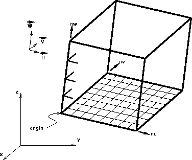
Figure 2 Notion of a GRID3 object in GOCAD. A 3-D grid in GOCAD is defined by its origin, the number of samples on each axis (nu, nv, nw), and three vectors
The small program I designed fills a 3-D grid with velocity values extracted from a GOCAD model file. The main idea is to make a loop over all the nodes of the grid located on the top row. From each point so defined, a shoot is performed vertically inside the model to locate the intersection points with all the interfaces of the model. Then each node of the column is filled with the value of the velocity attached to the domain corresponding to the location of the node.
The executable produced from this program receives a parameters file as input and generates an SEP output file. The syntax to run this program is
grid par=input.par > output.H
 |
The parameters file is written in a kind of SEP format. The script text below is an example of such a file:
project="ProjDiap.PJ" model="Diapir.pa"o1=7000.0 o2=3000.0 o3=0.0
d1=100 d2=100 d3=25
n1=150 n2=110 n3=200
vout=50 nout=60
The parameters file contains basically
An example of the results produced by the algorithm implemented is given in the next section. We have chosen this output arbitrarily. It is obvious that there exist many other possibilities for viewing the whole grid or part of it.