


We perform a prestack seismic impedance inversion on each of the three
synthetic surveys. The basis of the method is outlined here, and given
in more detail in Lumley and Beydoun (1991), and Lumley (1993).
The first step consists of estimating angle-dependent reflectivity
via a true-amplitude least-squares Kirchhoff prestack migration.
This is obtained by an l2 estimate of the ![]() coefficient in
constant offset sections at each subsurface point:
coefficient in
constant offset sections at each subsurface point:
| |
(14) |
and a separate l1 estimate of the reflection angles ![]() directly from the
data in constant offset sections at each subsurface point:
directly from the
data in constant offset sections at each subsurface point:
| |
(15) |
where D are the recorded seismic data.
To complete the final estimation of ![]() , we make a simple
set of mappings from the separate estimates of
, we make a simple
set of mappings from the separate estimates of ![]() and
and ![]() .A map of
.A map of ![]() can be obtained directly as:
can be obtained directly as:
| |
(16) |
Then, since there is a one-to-one mapping of ![]() to any point
to any point
![]() , and
, and ![]() to the same point
to the same point ![]() , there is a unique
map of
, there is a unique
map of ![]() and
and ![]() to
to ![]() such that:
such that:
| |
(17) |
which is the desired result. This completes the angle-dependent reflectivity estimation process.
Once we have estimated ![]() ,an inverse problem for three isotropic elastic
parameters can be posed. Under the assumption that relative contrasts
in material properties are small at reflecting boundaries, and the reflection
angles are well within the pre-critical region (Aki and Richards, 1980),
a linearization of the
Zoeppritz plane wave reflection coefficients can be made at every subsurface
point
,an inverse problem for three isotropic elastic
parameters can be posed. Under the assumption that relative contrasts
in material properties are small at reflecting boundaries, and the reflection
angles are well within the pre-critical region (Aki and Richards, 1980),
a linearization of the
Zoeppritz plane wave reflection coefficients can be made at every subsurface
point ![]() :
:
| |
(18) |
where ![]() are the relative contrasts in P impedance,
S impedance and
density at the reflecting boundary, and
are the relative contrasts in P impedance,
S impedance and
density at the reflecting boundary, and ![]() are known basis
functions which are analytical in
are known basis
functions which are analytical in ![]() . The three basis functions
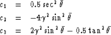
are plotted in Figure
. The three basis functions
are plotted in Figure ![[*]](http://sepwww.stanford.edu/latex2html/cross_ref_motif.gif) , with c1 at the top,
c2 at the bottom,
and c3 near the zero axis in the middle, and are given here analytically as:
, with c1 at the top,
c2 at the bottom,
and c3 near the zero axis in the middle, and are given here analytically as:
 |
||
| (19) |
where ![]() is the shear to compressional velocity ratio Vs/Vp.
We invert (18) at every subsurface location
is the shear to compressional velocity ratio Vs/Vp.
We invert (18) at every subsurface location ![]() by a least-squares method which bootstraps with offset and angle.
This yields an output section each of relative P and S impedance
contrasts.
by a least-squares method which bootstraps with offset and angle.
This yields an output section each of relative P and S impedance
contrasts.
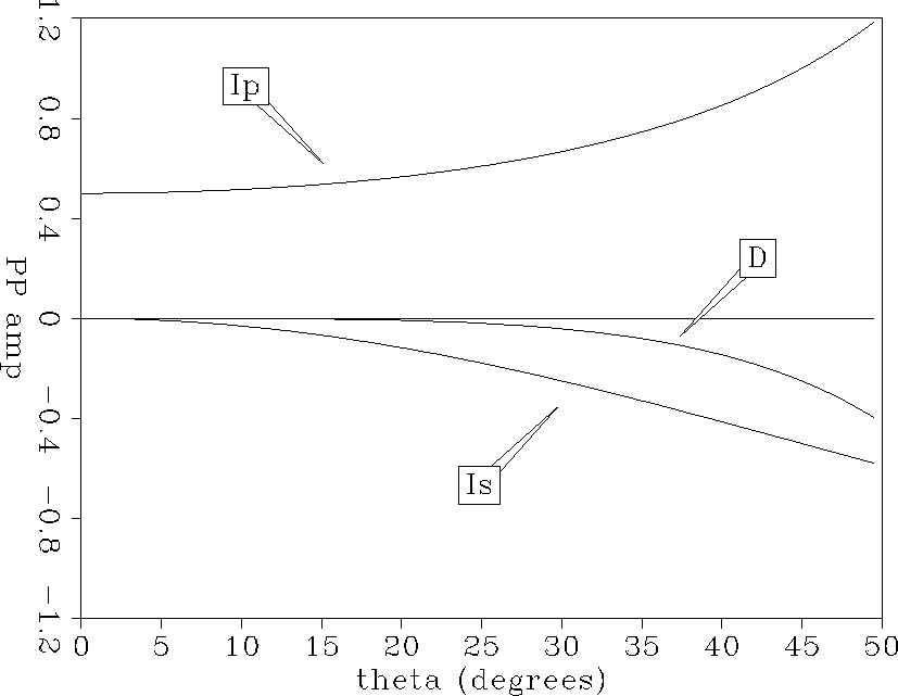 |

Figure shows the P impedance inversion difference section
for the two surveys before and after one time step of waterflood.
The waterflood zone at the top of the reservoir
shows the correct increase in P impedance at the well
location due to injection of water which is of higher P impedance than the
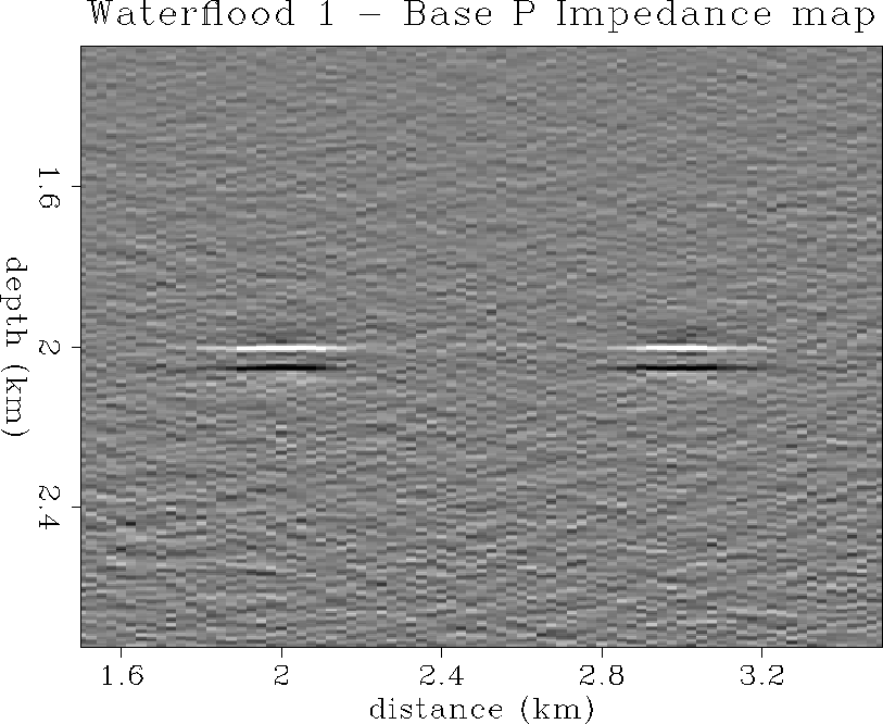
initial light oil in place at lower pore pressure. Figure
shows the impedance inversion difference section
for the two surveys before and after two time steps of waterflood
production. Again, the waterflood zone at the top of the reservoir
shows the correct increase in P impedance at the well, and the correct
lateral spatial extent.
We note that these P impedance sections resemble the migrated sections because,
to first order, a (migrated) stack approximates the normal incidence
P-P reflection coefficient in the absence of anomalous AVO. However,
the impedance inversion results are more accurate in terms of relative
impedance contrast estimates than a simple prestack imaging algorithm
in general.
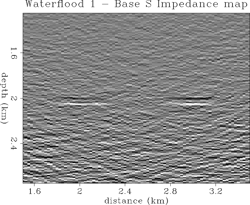
Figure shows the S impedance inversion difference section
for the two surveys before and after one time step of waterflood.
The waterflood zone at the top of the reservoir
shows the correct decrease in S impedance at the well
location due to injection of water which is of lower S impedance than the
initial light oil in place at lower pore pressure. However, the S impedance
results are much noisier than the P impedance results, which is expected since
they are most sensitive to the relatively fewer far offset trace data.
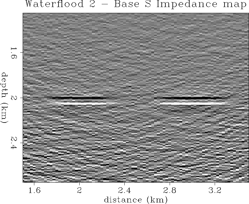
Figure
shows the S impedance inversion difference section
for the two surveys before and after two time steps of waterflood
production. Again, the waterflood zone at the top of the reservoir
shows the correct decrease in S impedance at the well, and the correct
lateral spatial extent, although in a somewhat more noisy manner.
Finally, the impedance inversions detected the correct opposite polarity changes in P and S impedance between the pre-waterflood survey and the post-waterflood surveys. These two parameters, instead of one single (potentially ambiguous) migrated or stacked reflection amplitude parameter, may be more diagnostic of changes in reservoir petrophysical properties over time-lapse monitor surveys. Furthermore, the magnitude of the impedance changes was recovered reasonably well in data having a significant noise level, since the change in S impedance between surveys is estimated from the data to be on the order of 1.5 times the magnitude of the change in the P impedance after waterflood production. Estimates of absolute or relative changes in the petrophysical properties themselves could be a very valuable tool in monitoring reservoir production processes.
 |


 |
 |
 |