

Next: Conclusions
Up: Karrenbach: Modeling nonlinear source-surface
Previous: Applicability
The previous paragraph described nonlinear source behavior of an
elastic medium that obeys the usual elastic anisotropic wave equation.
However a recent investigation by Walker 1993 shows
that the time dependence of
source-surface interactions of vibrators can be effectively described
using a nonlinear ``chaotic'' wave equation. Walker uses the well-known
Duffing equation to parameterize vibratory sources and nonlinear propagation
in the subsurface.
The one dimensional Duffing equation is given as:
|  |
(7) |
where  and
and  are adjustable parameters,
which govern the nonlinear behavior. u is a scalar quantity.
F is the strength of the periodic forcing function with
  being
the temporal frequency.
The time dependent solution u(t) of
the Duffing equation exhibits typical behavior for a wide range
of parameters. When the source-surface system is at a high energy level,
the amplitudes are large. Harmonics are then generated that
alter the high frequency part of spectrum of the original source wavelet.
When the amplitudes are low,
the nonlinear behavior creates
subharmonics, that introduce low frequency peaks.
Such a period doubling phenomenon is typical of chaotic equations.
The typical chaotic behavior, however, happens in bandlimited intervals
of the forcing function's spectrum. Outside that intervals,
the equation behaves pseudo regular.
The following Figures show some of that behavior. Unless otherwise noted the
parameters are set to zero. If you are viewing
the paper on the screen you can adjust parameters by yourself and
you will see immediately the result.
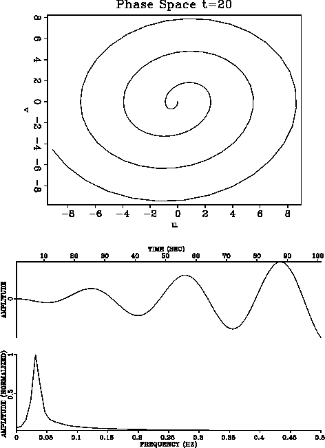
Figure 1 shows a constantly growing signal, due to a system that
is not damped or limited in any way.
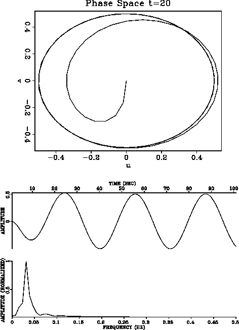
Figure 2 shows a damped linear system.
The phase space (displacement plotted
versus velocity) is a spiral approaching a constant orbit. The time domain
response is well behaved and the spectrum shows a single peak developed
around the center frequency of the forcing function.
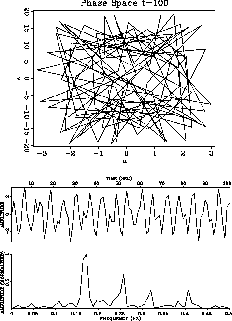
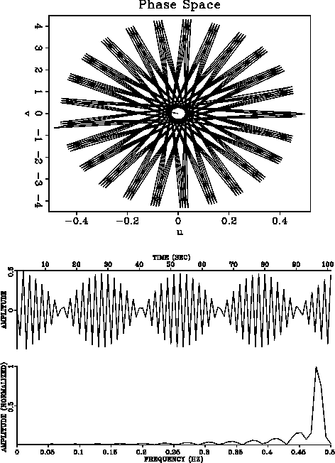
In Figure 3, some harmonic peaks are generated in the spectrum
beyond the peak of the forcing function. High amplitudes arise by
emphasizing the third order term in the equation.
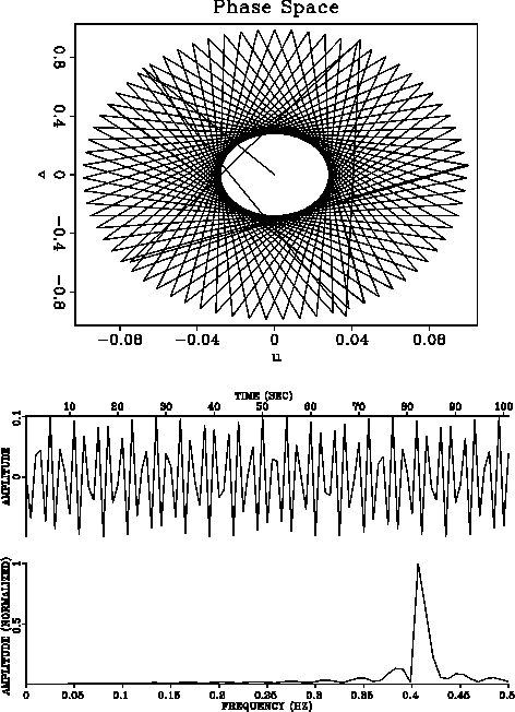
In Figure 4 subharmonic peaks are generated in the spectrum
below the peak of the forcing function.
Relatively low amplitudes are generated,
in contrast to Figure 3.
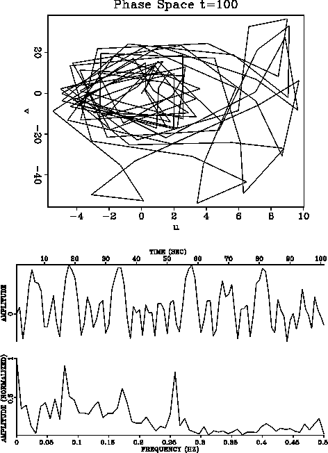
Nonlinear behavior is developing in Figure 5
at this parameter setting,
which is apparently erratic in the phase space. The spectrum of the
forcing function is changed in a non systematic way.
Compare this to the structured modifications in Figure 4
and 3.
Figure 6 and 7 show slightly different parameter
settings
and illustrate the unstable character of this equation. Small changes
in parameters produce large effects in the solution behavior.
undamped
Figure 1 Undamped Duffing equation with
 =1,
=1,  =0,
=0,  =0,
=0,  =1 and F=1.
The movement is linear and growing even after some initial time.


 damped
Figure 2 Damped Duffing equation with
 =1,
=1,  =0,
=0,  =2,
=2,  =1 and F=1.
The movement is linear and stable after some initial time.


 topharm
Figure 3 Duffing equation with
 =1,
=1,  =0,
=0,  =0,
=0,  =10
=10  =4.67 and F=1.
Harmonic peaks are generated in the spectrum beyond the peak of the forcing
function. High amplitudes arise by emphasizing the third order term in
the equation.


 subharm
Figure 4 Duffing equation with
 =1,
=1,  =0,
=0,  =0,
=0,  =0.67
=0.67  =4.67 and F=1.
Subharmonic peaks are generated in the spectrum below the peak of the forcing
function. Relatively low amplitudes are generated, in contrast to Figure 3.


 nonlin
Figure 5 Duffing equation with
 =1,
=1,  =0,
=0,  =2,
=2,  =10
=10  =1.0 and F=10.
Nonlinear behavior is developing at this parameter setting, which is apparently erratic in the phase space. The spectrum of the forcing functions changed in a non systematic way. Compare this to the structured modifications in Figure 4 and 3.


 nonlin2
Figure 6 Duffing equation with
 =1,
=1,  =0,
=0,  =2,
=2,  =10
=10  =10.0 and F=10.
Nonlinear behavior shows well developed structure in phase space,
but the spectrum shows signs of alternate peaks.


 nonlin3
Figure 7 Duffing equation with
 =1,
=1,  =0,
=0,  =2,
=2,  =10
=10  =9.3 and F=40.
A slight change in frequency and source strength compared
to Figure 6 shows totally different behavior
in phase space as well as in physical space.


The original Duffing equation describes a scalar chaotic process
and has been used in the past to model and analyze the effective
time behavior of a source-surface system.
I would like to extend the equation and use it for multi-component sources
in a 3-D medium. Formally, a 3-D 3-c Duffing equation reads then:
|  |
(8) |
I would like to investigate this equation further using finite difference
schemes to see
if for a reasonable choice of parameters source-surface effects can be
modeled.
It will be interesting to compare it to 9 component land data to see if
such source effects are indeed present in the data.
Finding the equivalent linear multi-component source function
would prove very useful
as a step towards backing source differences out of the data set.


Next: Conclusions
Up: Karrenbach: Modeling nonlinear source-surface
Previous: Applicability
Stanford Exploration Project
11/16/1997
