Nowadays, a standard industrial seismic processing almost always involves the constant-velocity dip moveout correction. Two main features make the process attractive. First, the computational cost is low compared to prestack migration in both two-dimensional and three-dimensional processings. Secondly, because constant-velocity dip moveout is ``independent of velocity'', it may come before velocity analysis, removing the effects of dip ().
However, the hypothesis of constant velocity is somewhat inconsistent with the concept of velocity analysis which results in the construction of a depth-variable velocity model. Recently, several methods for depth-variable velocity dip moveout (, , ) undeniably improved the zero-offset stack section. However, one can wonder if they clearly improve the result of the post-stack migrated section.
How variable velocity dip moveout improves post-stack migration
In this section I show that the depth-variable velocity dip moveout strongly differs from the constant-velocity dip moveout not by the shape of the operator (although the operator is squeezed horizontally when the velocity increases with depth (, )) but by the amplitude distribution along the operator. In the second section, a synthetic data example shows how the processing flow NMO-v(z) DMO-post-stack migration is comparable to pre-stack migration.
Some amplitude issues
Jakubowicz gave an elegant formulation of f-k dip moveout where a finite number of dips are processed separately and stacked according to equation (11),
| |
(11) |
| |
(12) |
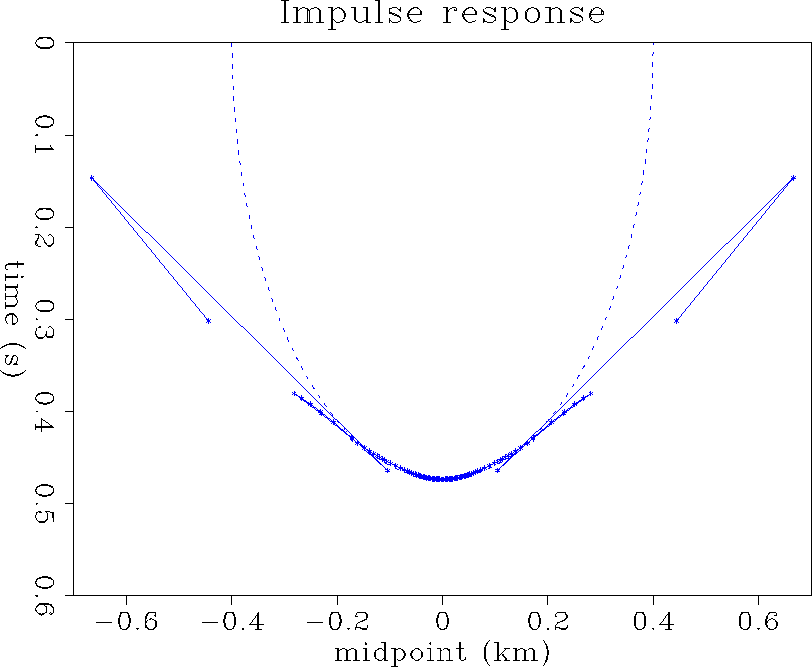
In the general case of depth-variable velocity, there is no analytic expression of the amplitude along the operator but the dip-decomposition method gives us a qualitative idea. Indeed, the operator of variable-velocity dip moveout may be build point by point for a range of dips regularly sampled. Then, a region where the points are close to each other allows a significant stack of the dipping segments of the operator, and thus corresponds to an area of high amplitude. Figure (imprs) shows an impulse response of dip moveout in a time-variable velocity model whose profile is represented in Figure (vel).
|
vel
Figure 16 Interval velocity model. | 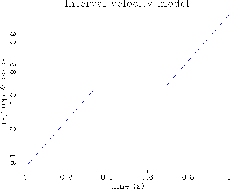 |
 |
Artley's v(z) dip moveout method
which produced Figure (imprs), requires a non-linear inversion
of a ![]() system of equations for each time, offset, and dip
we consider. Though it is a time consuming process, it provides us
with amplitude information. First, the triplication of the impulse
response have a low energy for this velocity model (a trough in the
velocity profile would show a high amplitude triplication). Secondly,
the amplitude varies a lot along the operator, starting high at gentle
dips, decreasing, and increasing again just before a triplication.
system of equations for each time, offset, and dip
we consider. Though it is a time consuming process, it provides us
with amplitude information. First, the triplication of the impulse
response have a low energy for this velocity model (a trough in the
velocity profile would show a high amplitude triplication). Secondly,
the amplitude varies a lot along the operator, starting high at gentle
dips, decreasing, and increasing again just before a triplication.
The shape of a v(z) DMO operator differs from the constant-velocity DMO operator essentially by a number of triplications along its branches (Figure (imprs)). However, since these triplications are generally low-amplitude, the shape is not the most discriminative feature of the operator. The amplitude variations along the operator strongly depend on the velocity model, and therefore play an important role in the dip moveout correction.
Comparison with constant-velocity dip moveout
There is no doubt that replacing the constant-velocity dip moveout step
by a variable-velocity dip moveout step improves the zero-offset section
after stack. However, the final result of a standard processing flow
is the post-stack migrated section. Thus, the idea of comparing the pre-stack
migrated section to the post-stack migrated sections with and without
the constant velocity assumption is natural. David Lumley
provided the synthetic data example that appears in the
next three figures. This synthetic model includes four diffractors
at various depth and midpoint positions, two horizontal events,
and a 45-degree dipping event, overlaid by a strong,
constant RMS-velocity gradient (![]() ).
).
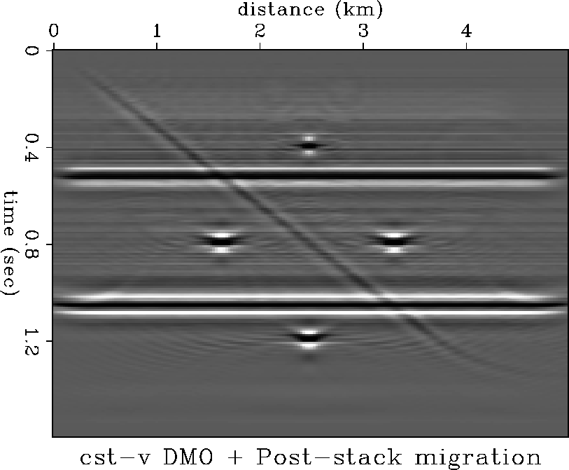
Results of constant-velocity DMO
The processing flow involving a constant-velocity dip moveout step is displayed in Figure (cvmig). The three deepest diffractors are unfocused whereas the shallow diffractor is focused but low-amplitude. The horizontal reflectors are well imaged but the dipping event has a lower amplitude than expected though it is not mispositioned.
 |
Results of approximate variable-velocity DMO
Castle proposes a method conceptually similar to
Hale's squeezed dip moveout operator
but different in its implementation. Instead of applying
a standard normal moveout correction (![]() )followed by a dip moveout correction with a squeezed operator, the method
uses de Bazelaire's normal moveout
correction with shifted hyperbolae:
)followed by a dip moveout correction with a squeezed operator, the method
uses de Bazelaire's normal moveout
correction with shifted hyperbolae:
| (13) |
| t0 = tp S | (14) |
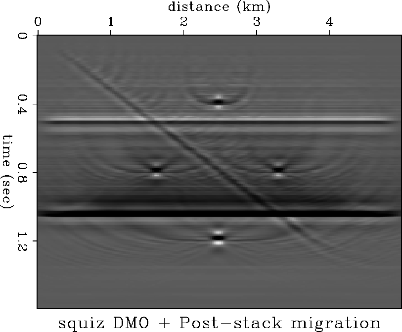
Figure (svmig) results from post-stack migration after the approximate dip moveout step. The four diffractor points are better focused with this flow than with the flow that involves constant-velocity dip moveout. Unfortunately, the method, apart from approximating the shape, also simplifies the amplitude distribution along the operator. The dull appearance of the reflectors is a consequence of this improper handling of the amplitudes.
 |
Result of variable-velocity DMO
For this processing flow, I use the variable-velocity DMO algorithm
developed by Artley . The method, accurate for
any depth-variable velocity media, solves a system of equation
accounting for the location and the dip of any reflector point.
An extension of this system to three dimensions is proposed in the
next section (page ![[*]](http://sepwww.stanford.edu/latex2html/cross_ref_motif.gif) ).
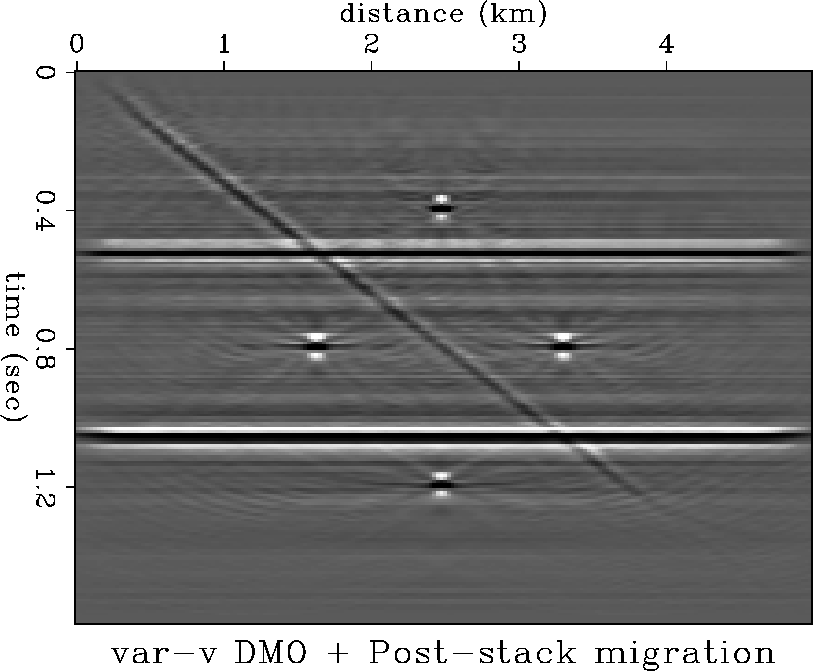
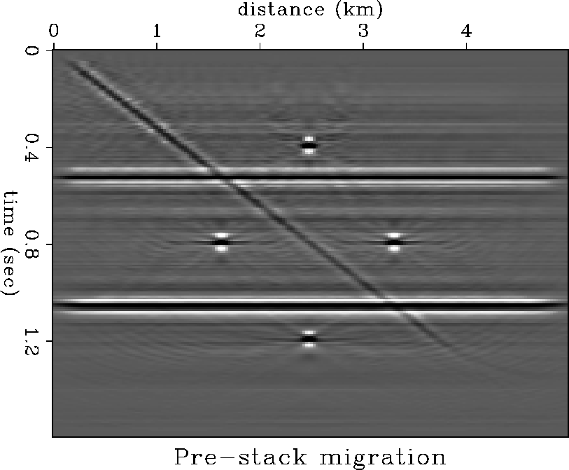
The similarity between the pre-stack migration (Figure (psmig))
and the post-stack migration after depth-variable velocity dip moveout
Figure (vvmig) is not surprising because the two processing are
equivalent when there is no lateral velocity variation. However, the
clear improvement with respect to the standard processing makes the
variable-velocity dip moveout a very useful tool.
).
The similarity between the pre-stack migration (Figure (psmig))
and the post-stack migration after depth-variable velocity dip moveout
Figure (vvmig) is not surprising because the two processing are
equivalent when there is no lateral velocity variation. However, the
clear improvement with respect to the standard processing makes the
variable-velocity dip moveout a very useful tool.
 |
 |
Conclusion
The main difference between constant-velocity and variable-velocity
dip moveout is not the shape of the operator but the amplitude
distribution. Because this distribution highly depends on the
velocity model, variable-velocity dip moveout considerably
improves the post-stack migration. However, the drawback is its high
computational cost. For example, Artley's method is more costly
than a pre-stack migration, because the algorithm does much more
than compute the zero-offset traveltime: it performs a ray-based
pre-stack migration and uses the computed zero-offset traveltime
to apply the dip moveout correction. Because both Meinardus's and Artley's
algorithms are based on the dip-decomposition idea, it is possible
to reduce the computational cost by cutting down the number of dips
to process. On the other hand, Castle's method differs from the
constant-velocity dip moveout flow by involving an extra time-variable
shift of the data. At a small additional computational cost, the
approximate dip moveout flow improves the quality of imaging after
post-stack migration. Furthermore, this method can be adapted in
three dimensions by using the constant-velocity algorithm described
in the first part (page ![[*]](http://sepwww.stanford.edu/latex2html/cross_ref_motif.gif) ).
).
Apart from all speed considerations, a precise dip moveout method requires both assumptions of a depth-variable velocity and a three-dimensional model. The next section explains how Artley's two-dimensional depth-variable velocity dip moveout method can be extended to three dimensions.
Equations for three-dimensional dip moveout
in depth-variable velocity media
Artley introduced an original method to perform v(z) dip moveout in a two-dimensional earth model. The process uses ray tracing tables and solves a system of equations accounting for the location and the dip of the reflection point. This section describes an extension of Artley's method and derives a new set of equations for the 3-D case.
The ray parameter in three dimensions
In a two-dimensional earth model, the ray parameter is given at any point of the ray by the relationship
| |
(15) |
| |
(16) |
Deriving the system of equations
Vectorial relationships on the earth's surface
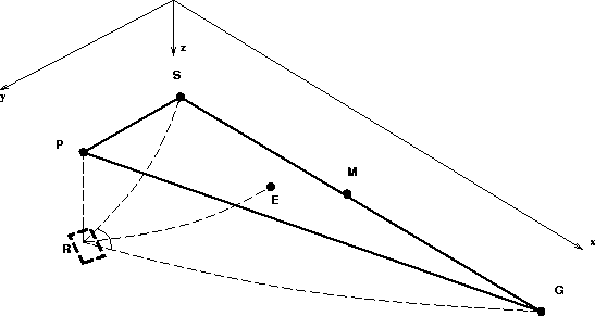
In the triangle (PSG) in Figure (Rayp3d), the following expression relates the horizontal traveling of the source and geophone rays with the offset:
| |
(17) |
![[*]](http://sepwww.stanford.edu/latex2html/foot_motif.gif) .
The projection on the earth's surface of a
ray path (of parameter p and traveltime t) is the 2-D vector
.
The projection on the earth's surface of a
ray path (of parameter p and traveltime t) is the 2-D vector
| |
(18) |
A second relation expresses the coordinates of the point of emergence of the zero-offset ray, E. In the triangle (PEM), we have :
| |
(19) |
| |
(20) |
 |
Time relationships in the earth's interior
The following obvious equation relates the traveltimes along the ray paths to source and geophone, ts and tg, to the given total traveltime tsg:
| ts + tg = tsg . | (21) |
We can also state two more equations to account for the fact that the three ray paths, namely the zero-offset, source, and geophone ray paths, end at the same point in depth (R):
| |
(22) |
The relationship between the ray paths
At the reflector point R, the ray must obey Snell's law. In other words,
the angle of incidence must equal the angle of reflection. In terms of
ray paths, ![]() fixes the position of the reflection plane,
and
fixes the position of the reflection plane,
and ![]() and
and ![]() account for the angles of incidence and
reflection. Since
account for the angles of incidence and
reflection. Since ![]() and
and ![]() have equal lengths
1/v, Snell's law can be expressed in the following vectorial form:
have equal lengths
1/v, Snell's law can be expressed in the following vectorial form:
| |
(23) |
| |
(24) |
| |
(25) |
| |
(26) |
| |
(27) |
Sets of equations and unknowns Our system of equations is constituted by collecting relations (18), (20), (21), (22), and (27):
 |
(28) |
The unknowns are ![]() ,
, ![]() , ts, tg, t0, and
, ts, tg, t0, and
![]() . As described in the preamble, the
. As described in the preamble, the ![]() vectors
have only two unknown parameters, px and py (or p and
vectors
have only two unknown parameters, px and py (or p and ![]() ).
Similarly,
).
Similarly, ![]() is a two-dimensional unknown vector. Therefore,
system (28) relates nine unknowns with the known parameters
is a two-dimensional unknown vector. Therefore,
system (28) relates nine unknowns with the known parameters
![]() , tsg,
, tsg, ![]() ,
, ![]() , and the ray tracing
tables
, and the ray tracing
tables ![]() ,
, ![]() , and
, and ![]() .
.
Solving the system
The second relation of system (28) can be isolated
because it simply adds two relations and two unknowns (the
coordinates of ![]() ). Similarly, the third equation
can be substituted into the others by replacing ts (or tg)
with tsg - tg (or tsg - ts).
). Similarly, the third equation
can be substituted into the others by replacing ts (or tg)
with tsg - tg (or tsg - ts).
Thus, we obtain a reduced system of four relations (six equations):
 |
(29) |
| |
(30) |
| ts = tsg - tg . | (31) |
Agreement with the equations in two dimensions
The 2-D system derived by Artley is a set of four equations with four unknowns. It can be retrieved by replacing the vectorial ray parameters with their scalar form (since the vectors are now in a common plane). The first relation of system (28) then becomes
| |
(32) |
| |
(33) |
| |
(34) |
| |
(35) |
Conclusion
We![[*]](http://sepwww.stanford.edu/latex2html/foot_motif.gif) derived a set of equations that
constrains the travel path
of a ray in a three-dimensional earth model with a depth-variable
velocity. This system can be solved for the zero-offset traveltime
and the emergence point of the ray, yielding an efficient method
for dip moveout processing. A successful implementation
of the equations have been realized by Artley at the Colorado School
of Mines, showing the expected saddle-like impulse response.
derived a set of equations that
constrains the travel path
of a ray in a three-dimensional earth model with a depth-variable
velocity. This system can be solved for the zero-offset traveltime
and the emergence point of the ray, yielding an efficient method
for dip moveout processing. A successful implementation
of the equations have been realized by Artley at the Colorado School
of Mines, showing the expected saddle-like impulse response.
CONCLUSIONS The dip moveout correction requires important compromises between speed and precision in two- and three-dimensional models.
The conclusions to part I (page ![[*]](http://sepwww.stanford.edu/latex2html/cross_ref_motif.gif) ) propose ways
of increasing the speed. The constant-velocity assumption allows
the dip moveout process to be fast in both two- and three-dimensional
model geometries. Some additional attributes of the operator, such
as weighting and anti-aliasing schemes, reduce the amplitude artifacts
in a computationally efficient manner. Moreover, parallel computing
can speed up the process even in the case of three-dimensional
land data where the acquisition geometry is irregular. A parallel
implementation of integral dip moveout in time slices proves
efficient for irregular azimuthal distribution of the data.
) propose ways
of increasing the speed. The constant-velocity assumption allows
the dip moveout process to be fast in both two- and three-dimensional
model geometries. Some additional attributes of the operator, such
as weighting and anti-aliasing schemes, reduce the amplitude artifacts
in a computationally efficient manner. Moreover, parallel computing
can speed up the process even in the case of three-dimensional
land data where the acquisition geometry is irregular. A parallel
implementation of integral dip moveout in time slices proves
efficient for irregular azimuthal distribution of the data.
The second part of this paper proposes two ways of improving precision. The first is to apply a proper weight along the operator, which is achieved at almost no extra computational cost. The second way is to consider depth-variable velocity. The dip moveout correction then becomes computationally expensive. However, an approximation valid for gently dipping reflectors allows the variable-velocity process to be almost as fast as the constant-velocity process. Aside from the considerations of speed, the method of three-dimensional dip moveout in depth-variable velocity developed in the last section may considerably improve the imaging of complex data structures.
Throughout my analysis of the dip moveout correction, I have tried to optimize both speed and precision. Unfortunately, the very fast methods prove inaccurate, whereas the very precise ones are slow. The approximate methods related to the squeezing of the dip moveout operator turn out to be fast and rather precise, even in three dimensions. This result suggests a method for three-dimensional dip moveout processing: the operator with limited cross-line extension that I introduced in the first part can be squeezed, yielding a first-order approximation of the theoretic ``saddle'' operator.
ACKNOWLEDGMENTS I would like to thank David Lumley for many useful discussions and for providing me with synthetic data and code. I am grateful to Mihai Popovici and Biondo Biondi for their efforts to transmit their knowledge of DMO and for their useful hints on parallel programming. I also thank Dave Nichols for his patience in teaching me the basis of parallel processing. Dimitri Bevc and David Lumley helped clarify for me the idea of anti-aliasing with triangle convolution. In addition, I would like to thank Craig Artley, Mihai Popovici, and Matthias Schwab for working with me on the derivation of the equations of 3-D v(z) DMO. Finally, I am grateful to Professor Jon Claerbout and Stew Levin for providing an excellent environment for my research, and to the Total oil company for funding it.
[SEP,SEGCON,SEGBKS,GEOTLE,EAEG,MISC,mybib]