 |
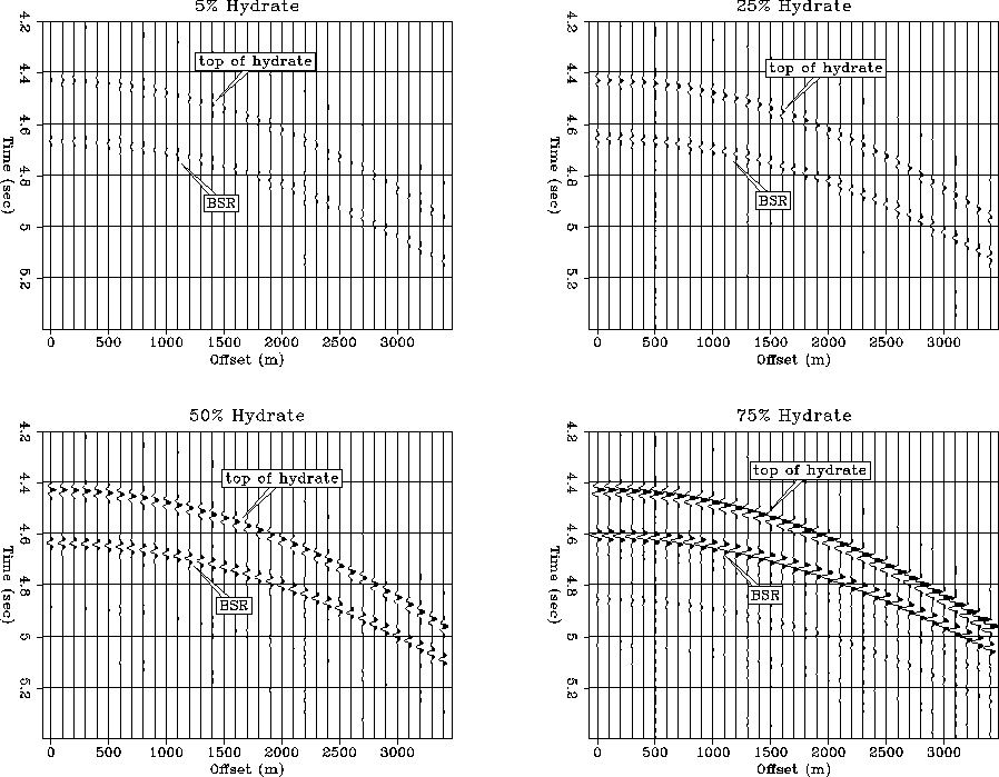
Figure 8 Synthetic seismograms for hydrate deposited in the pores with different hydrate saturations overlaying brine-saturated sandstone.
After evaluating the effect of hydrate cementation on the seismic amplitudes and reflection responses, we performed the same modeling procedure for the case of hydrate deposition in the pore space only. As before, we modeled two cases. In one case, the hydrate is overlaying brine-saturated sandstone, while in the other case the hydrate is overlaying gas-saturated sandstone.
Figure 8 shows the synthetic seismograms for different hydrate saturations in the case where the hydrate is underlain by brine sandstone. The reflection signals are caused by the top and the bottom of the hydrate zone. As described in the previous section, the signal at the BSR has reversed polarity, and the amplitudes of the reflectors become stronger with increasing hydrate saturation. Since small amounts of hydrate saturation do not affect the velocities significantly, there are barely reflection signals for hydrate saturations less than 50%. Considering noise contamination in real seismograms, these signals would not be visible. For hydrate saturations more than 50%, the top and bottom show strong amplitudes. The BSR signal appears to increase slightly with increasing offset.
 |
 |
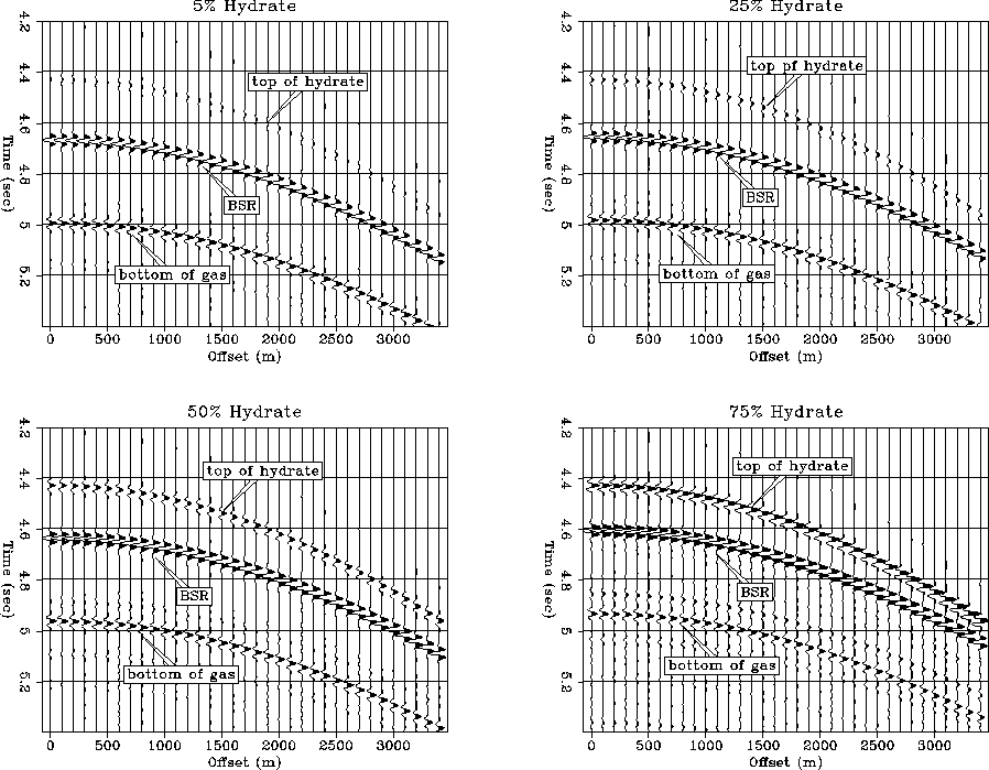
Figure 9 illustrates the synthetic seismograms resulting in the case where the hydrate-bearing sandstone is overlaying gas-saturated sandstone. The visible reflections are again caused by the top and bottom of the hydrate and additionally by the bottom of the gas layer. In contrast to the case of brine saturation, the BSR already displays strong reflection amplitudes for only small amounts of hydrate saturation. This is caused by the higher velocity contrast between hydrate and gas-saturated sandstone. The top of the hydrate results, as before, in small reflection amplitudes for small hydrate saturation and increasing amplitudes with increasing saturation. For hydrate saturations less than 50% these amplitudes are in fact barely visible and would not be resolved in reality. The amplitudes at the BSR appear to be increasing with increasing offsets.
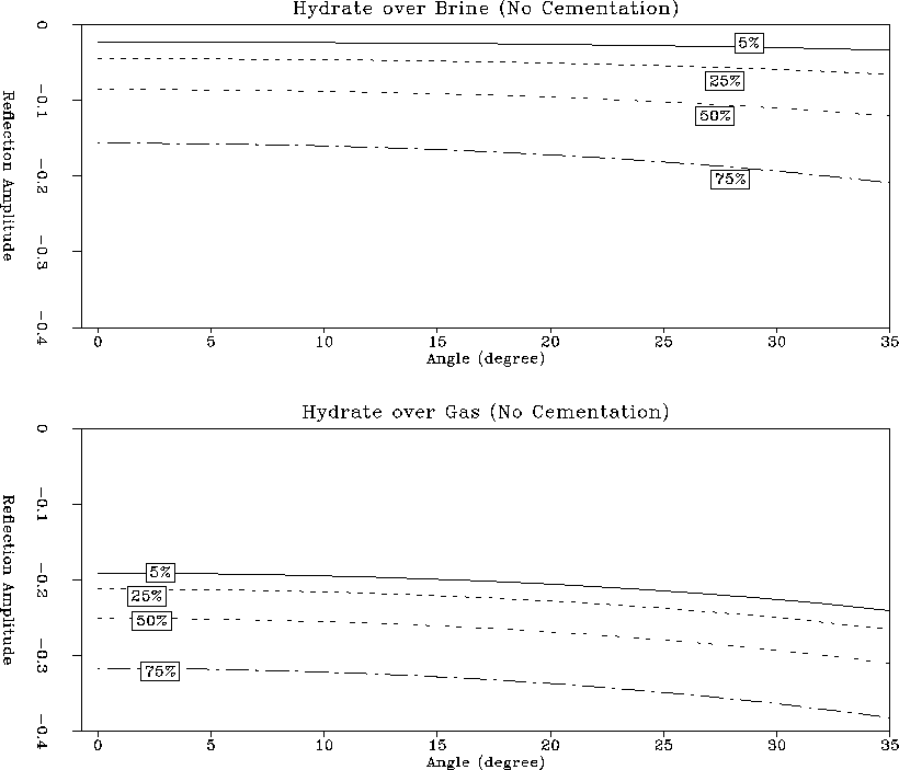
We again used Zoeppritz equations to calculate the actual AVO responses at the BSR and to compare them with each other. The results can be seen in Figure 10. The upper panel shows the amplitude behavior for hydrate overlaying brine sandstone, the lower panel shows the amplitudes resulting from hydrate overlaying gas-saturated sandstone.
It is obvious that the amplitude behavior in both cases is opposite to the amplitude behavior displayed when the hydrates were deposited as cement. The relatively small zero-offset reflection amplitudes for hydrate overlaying brine reflect the absence of a significant P-wave velocity contrast in this case. The amplitude trend shows increasingly negative amplitudes with increasing offset. Since the S-wave velocity in the hydrate decreases only slightly relative to the one in brine with increasing hydrate saturation, we can attribute this effect mainly to the P-wave velocity contrast. For only small amounts of hydrate saturation, the increase in amplitude is relatively small. It becomes more pronounced the more hydrate is present in the hydrate layer. In the case where the hydrate is overlaying gas-saturated sediment, the zero-offset reflection amplitude is higher. Furthermore, only small amounts of hydrate saturation have a stronger effect on the AVO response.
It will be difficult to discriminate between sediment containing a significant amount of hydrate overlaying brine sediment and sediment containing only a small amount of hydrate overlaying gas sediment from the reflection responses alone. Additional information from seismic velocity analysis, on the other hand, should make such a distinction possible.
 |