


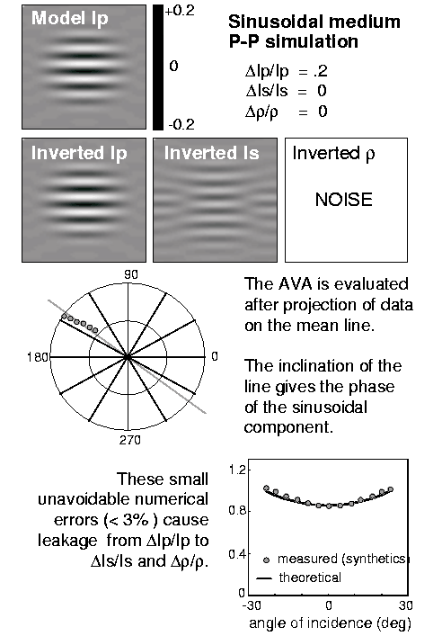
The first model is a single sinusoidal perturbation of P-impedance
(Figure 6). In the transformed domain, it is represented by
an impulse, broadened because of the windowing in the spatial domain.
The data are synthetic seismograms for P-P reflections.
Figure (6) shows the
AvA and the PvA extracted from the data in the transformed domain
for the point corresponding to the sinusoidal medium.
They are compared with the theoretical AvA and PvA.
The small unavoidable numerical errors (less than 3%) cause leakage from
![]() to
to ![]() and
and ![]() .Consequently, the estimate of S-impedance and density from P-P
reflections is unreliable even with synthetic data.
.Consequently, the estimate of S-impedance and density from P-P
reflections is unreliable even with synthetic data.
 |

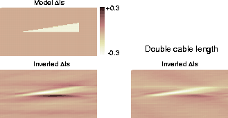
The second model (Figure 7) mimics a fault with a gas-bearing sand target in the upper part, where P-impedance and S-impedance variations occur.
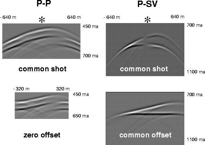
We have evaluated synthetic common shot gathers for P-P and P-SV reflections; some gathers are shown in Figure 8. The position of the source is indicated by a star. Acquisition geometry is reported in Figure 7.
|
fault
Figure 7 Model and acquisition parameters. | 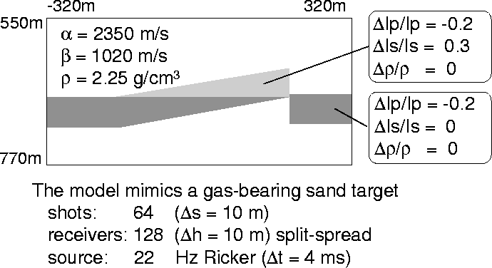 |
 |
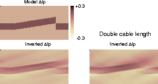
Inversion of P-P data allows an accurate reconstruction of P-impedance perturbation (Figure 9). Due to the limited observation angle, horizontal variations cannot be recovered. We have increased the maximun incident angle by doubling the cable length. The inversion gives similar results (Figure 9, right): P-impedance estimation is mainly governed by normal incidence.
S-impedance inversion from P-P data is masked by P-impedance leakage (Figure 10). If we use P-SV data, S-impedance perturbation is correctly recovered (Figure 11). The accuracy increases by doubling the cable length. In fact, for normal incidence, the P-SV reflection coefficient vanishes (Figure 5): S-impedance estimation improves with higher incident angles.
 |
|
invIs-PP
Figure 10 Inversion of | 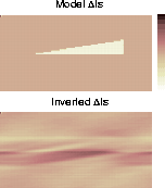 |
 |