

Next: Conclusions
Up: Fomel & Biondi: Azimuth
Previous: Proposed technique
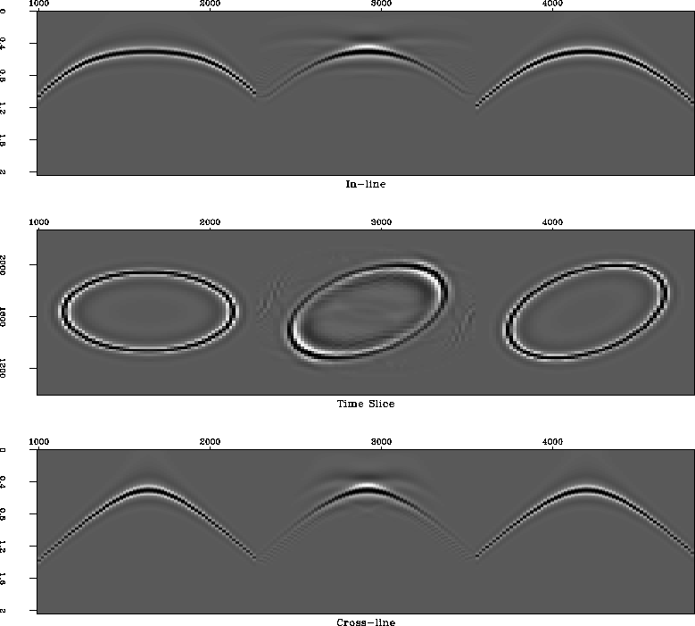
Our first synthetic test of the AMO operator is a simple diffraction
in a constant velocity medium. We modeled a common-azimuth data set
over a diffraction point with an offset of 500 meters and a regular
midpoint grid 20 by 20 meters. The AMO operator was designed to rotate
the offset azimuth of the data by 30 degrees. The results are compared
with the modeled data in Figure 17. Azimuth moveout has
succeeded in reconstructing the true geometry of the desired output,
though it did not behave perfectly with respect to the amplitudes and
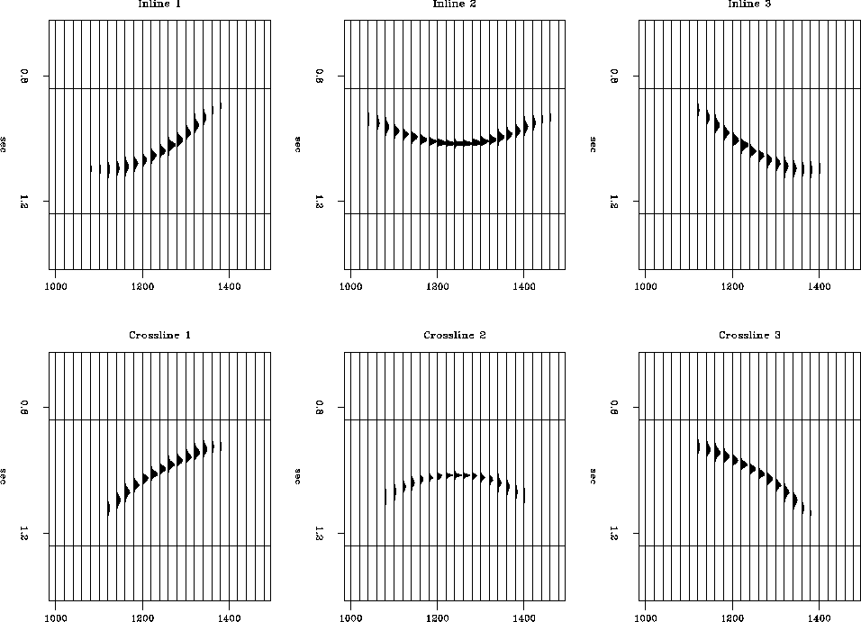
boundary effects. The corresponding AMO impulse response is shown in
crossline and inline sections in Figure 18. For simplicity,
this impulse response doesn't include the derivative filter required
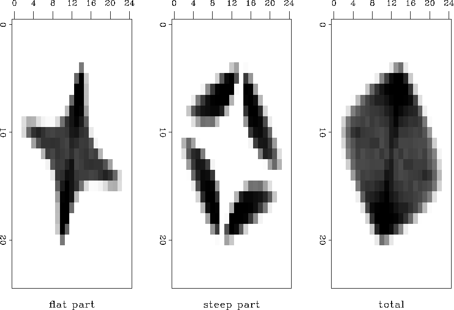
for the complete definition of AMO. Figure 19 illustrates
the antialising applied to AMO. The ``top'' view in the time direction
shows how the antialiased AMO operator is constructed from the
flat-dip and steep-dip parts.
amoimp
Figure 17 Diffraction test on
azimuth moveout. Left is the input, right is the desired output,
middle is the output of AMO.


 amoimr
Figure 18 AMO impulse response in
crossline (bottom) and inline (top) sections. The AMO geometry corresponds
to h1=500 meters, h2=500 meters,  =0, and
  =30
degrees. The derivative filter is not included.


 amocon
Figure 19
``Top'' view on the antialiased AMO operator (stacked time slices.)
The AMO impulse response is created by superposition of the flat-dip
and steep-dip parts.


Next: Conclusions
Up: Fomel & Biondi: Azimuth
Previous: Proposed technique
Stanford Exploration Project
11/12/1997


