

Next: Time domain
Up: CROSS-EQUALIZATION
Previous: CROSS-EQUALIZATION
In the frequency domain, the problems of bandwidth equalization and
phase matching are orthogonal, since they are concerned with the
amplitude and argument of a complex signal.
The steps I applied to equalize the bandwidth were:
Fourier transform the training windows, S1 and S2, on the time-axis,
and calculate their spectra,  and
and  , where
|  |
(1) |
I then designed the desired spectrum of the output,  , by
simply taking the minimum of the two spectra at each frequency.
|  |
(2) |
I applied this filter to shape the spectra of the regions of interest
|  |
(3) |
The  in the denominator is purely for the event
 , since in this formalism
 .
.
As well as calculating a spectral operator,  , I calculated
the average difference in phase between the training windows for each
frequency,
  .
.
|  |
(4) |
This was then applied to map S2 onto S1
|  |
(5) |
Although the phase and bandwidth are orthogonal, in this approach it
does matter the order in which the corrections are
applied. This is due to the fact I calculate the average phase as the phase of
the average value, as opposed to the average of the phases. With my
approach it is correct to apply the bandwidth correction before the
phase correction, although this is unlikely to be very important.
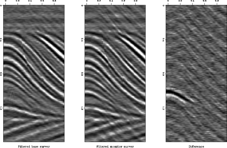
The results of the frequency domain cross-equalization are displayed
in Figure 3. The differences due to the fluid movements are
clearly visible, and the signal-to-noise level is high.
freq
Figure 3
Results of frequency domain cross-equalization. Left is filtered base
survey, center is filtered monitor survey and right is the difference.
The synthetic fluid layer is clearly visible in the difference
section. S/N = 9.14.


Next: Time domain
Up: CROSS-EQUALIZATION
Previous: CROSS-EQUALIZATION
Stanford Exploration Project
11/11/1997
![]() and
and ![]() , where
, where
![]() , I calculated
the average difference in phase between the training windows for each
frequency,
, I calculated
the average difference in phase between the training windows for each
frequency, ![]() .
.
