First consider wave resonance in a layer. Let the travel time through the layer and back again be given by the delay operator Z. The situation is shown in Figure 4. The wave seen above the layer has the form
It is no accident that the infinite series may be summed. We will soon see that for n layers the waves, which are of infinite duration, may be expressed as simple polynomials of degree n. We will consider many layers and the general problem of determining waves given reflection coefficients and determining reflection coefficients given waves.
|
8-4
Figure 4 Some rays corresponding to resonance in a layer. | 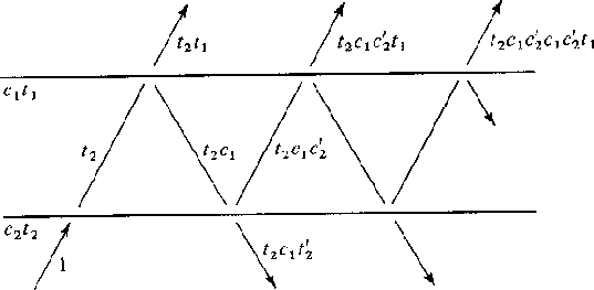 |
The reflection and transmission coefficients show one how to calculate the waves resulting from a wave impinging on a layer. Equation (11) relates to Figure 5 and shows how from the waves U an D' one extrapolates into the future to get U' and D.
| |
||
| (11) |
|
8-5
Figure 5 Waves incident and reflected from an interface. | 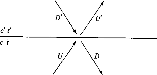 |
Let us rearrange (11) to get U' and D' on the right and U and D on the left. Then we will have an equation which extrapolates from the primed medium to the unprimed medium. We get
which may be arranged in the matrix form
![\begin{eqnarraystar}
\left[
\begin{array}
{ll}
-t & 0 \\ -c & 1 \end{array} \r...
...ght]
\; \left[
\begin{array}
{c}
U \\ D \end{array} \right]'\end{eqnarraystar}](img12.gif) |
Now premultiplying by the inverse of the left-hand matrix
![\begin{eqnarraystar}
\left[
\begin{array}
{c}
U \\ D \end{array} \right]
& = ...
...ht]
\; \left[
\begin{array}
{c}
U \\ D \end{array} \right]'\end{eqnarraystar}](img13.gif) |
||
finally getting the result, an equation to extrapolate from the primed medium to the unprimed medium.
![\begin{displaymath}
\left[
\begin{array}
{c}
U \\ D \end{array} \right]
\eq {1...
...ight]
\; \left[
\begin{array}
{c}
U \\ D \end{array} \right]'\end{displaymath}](img14.gif) |
(12) |
Now let us consider the Goupillaud type layered medium shown in Figure 6. For this arrangement of layers, (12) may be written
![\begin{eqnarraystar}
\left[
\begin{array}
{c}
U \\ D \end{array} \right]_{k+1}...
...
\begin{array}
{c}
U \\ D \end{array} \right]'_{k} \nonumber\end{eqnarraystar}](img15.gif) |
|
8-6
Figure 6 Goupillaud-type layered medium (layers have equal travel time). | 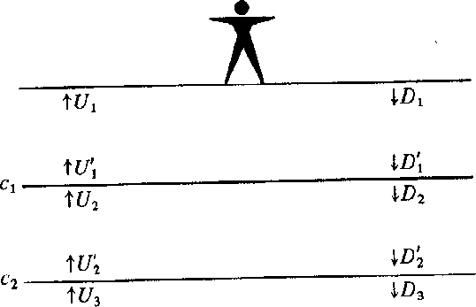 |
Let ![]() where T, the two-way travel time,
equals the data sampling interval.
Clearly,
multiplication by
where T, the two-way travel time,
equals the data sampling interval.
Clearly,
multiplication by ![]() is equivalent to delaying
a function by T/2,
the travel time across a layer.
This gives in the kth layer a relation between
primed and unprimed waves.
is equivalent to delaying
a function by T/2,
the travel time across a layer.
This gives in the kth layer a relation between
primed and unprimed waves.
![\begin{displaymath}
\left[
\begin{array}
{l}
U \\ D \end{array} \right]'_k
\eq...
...ght]
\; \left[
\begin{array}
{c}
U \\ D \end{array} \right]_k\end{displaymath}](img18.gif) |
(13) |
Inserting (13) into (12) we get a layer matrix
![\begin{eqnarray}
\left[
\begin{array}
{c}
U \\ D \end{array} \right]_{k+1}
& ...
...ight]
\; \left[
\begin{array}
{c}
U \\ D \end{array} \right]_k\end{eqnarray}](img19.gif) |
||
| (14) |
If there is energy flowing through a stack of layers,
there must be the same total flow through the kth
layer as through the (k + 1)st layer.
Otherwise,
there is an energy sink or source at the layer boundary.
The net upward flow of energy (energy flux)
at any frequency ![]() in the kth layer is given by
in the kth layer is given by
| |
(15) |
To establish that this is indeed independent of k,
we take the Hermitian conjugate
(transpose and conjugate with respect to real ![]() )of (14).
)of (14).
| |
(16) |
Now combine (14) with (16) in the form
![\begin{eqnarray}
&& \left[ U \left( {1\over Z} \right)
D \left( {1\over Z} \rig...
... \left[
\begin{array}
{c}
U \\ D \end{array} \right]_k \nonumber\end{eqnarray}](img23.gif) |
||
| (17) | ||
Since (1 - ck2)/tk2 = t'k/tk = Yk /Yk+1 this may be rewritten as the desired result, namely
| |
(18) |
Equation (18) says that at each frequency
![]() the energy flowing through the kth layer
equals the energy flowing through the
(k + 1)st layer.
the energy flowing through the kth layer
equals the energy flowing through the
(k + 1)st layer.
|
8-7
Figure 7 Basic reflection seismology geometry. The person initiates an impulse going downward. The earth sends back -R(Z) to the surface. Since the surface is perfectly reflective, the surface sends R(Z) back into the earth. Escaping from the bottom of the layers is a wave E(Z) which is heading toward the other side of the earth. | 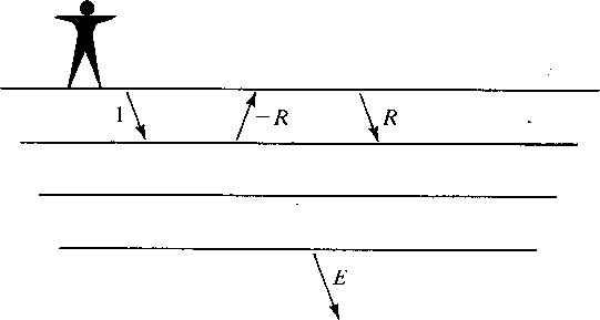 |
This energy flux theorem leads quickly to some sweeping statements about the waveforms scattered from layered structures. Figure 7 shows the basic geometry of reflection seismology. Applying the energy flux theorem to this geometry we may say that the energy flux in the top layer equals that in the lower halfspace so
| |
(19) |
This very remarkable result says that if we were to observe the escaping wave E(Z), we could by autocorrelation construct the waveform seen at the surface. We will later see that E(Z) is minimum-phase so that E could be constructed from R by spectral factorization.
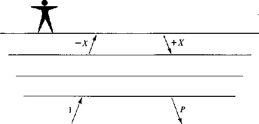
Now let us turn our attention to the earthquake seismology geometry depicted in Figure 8. Applying the energy flux theorem to this geometry we obtain
![]()
| |
(20) |
The interpretation of the result is that the backscattered waveform P(Z) has the form of an all-pass filter. This result may have been anticipated on physical grounds since all the energy which is incident is ultimately reflected without attenuation; thus the only thing which can happen is that there will be frequency-dependent delay.
 |
Finally, we will derive a theorem which relates energy flux to impedance and admittance functions (these functions have Fourier transforms with a positive real part). Suppose that a downgoing wave D(Z) is stronger than an upgoing wave U(Z) at all frequencies, i.e.
| |
(21) |
(Note that this does not imply |dt| > |ut|.) We will abbreviate (21) by
| |
(22) |
From (21) or (22) we will deduce that (D-U)/(D+U) has a Fourier transform with a positive real part. We have
 |
||
| (23) |
The numerator of (23) is positive by hypothesis (22) and the denominator of (23) is positive, since it is the spectrum of the time function dt + ut and any spectrum is always positive. Thus (D - U)/(D + U) is called ``positive real." The acoustical interpretation of (D - U)/(D + U) is that (D - U) represents the vertical component of material velocity and (D + U) represents the material pressure.