

Next: Velocity picking and slicing
Up: Fomel: Velocity continuation
Previous: Introduction
Velocity continuation in the zero-offset (post-stack case) can be
performed with a simple Fourier-domain algorithm
Fomel (1998):
- 1.
- Input an image, migrated with velocity v0.
- 2.
- Transform the time axis t to the squared time coordinate:
 .
. - 3.
- Apply a fast Fourier transform (FFT) on both the squared time
and the midpoint axis. The squared time
 transforms to the
frequency
  , and the midpoint coordinate x transforms to
the wavenumber k. We can safely assume that in the
post-migration domain seismic images are uniformly sampled in x,
which allows us to use the FFT technique. In the case of 3-D data,
FFT should be applied in both midpoint coordinates.
- 4.
- Apply a phase-shift operator to transform to different velocities v:
|  |
(1) |
- 5.
- Apply an inverse FFT to transform from
 and k to
 and x.
- 6.
- Apply an inverse time stretch to transform from
 to t.
to t.
The computational complexity of this algorithm has the same order as
that of the Stolt migration Stolt (1978), but in practice
it can be even faster because of the very simple inner computation.
To generalize algorithm (1) to the prestack case, we
first need to include the residual NMO term Fomel (1996).
Residual normal moveout can be formulated with the help of the
differential equation:
|  |
(2) |
where h stands for the half-offset. The analytical solution of
equation (2) has the form of the residual NMO
operator:
|  |
(3) |
After transforming to the squared time  and the
corresponding Fourier frequency
  , equation
(2) takes the form of the ordinary differential
equation
|  |
(4) |
with the analytical frequency-domain phase-shift solution
|  |
(5) |
To obtain a Fourier-domain prestack velocity continuation algorithm,
we just need to combine the phase-shift operators in equations
(1) and (5) and to include
stacking across different offsets. The algorithm takes the following form:
- 1.
- Input a set of common-offset images, migrated with velocity v0.
- 2.
- Transform the time axis t to the squared time coordinate:
 .
. - 3.
- Apply a fast Fourier transform (FFT) on both the squared time
and the midpoint axis. The squared time
 transforms to the
frequency
  , and the midpoint coordinate x transforms to
the wavenumber k.
- 4.
- Apply a phase-shift operator to transform to different velocities v:
|  |
(6) |
To save memory, the continuation step is immediately followed
by stacking.
- 5.
- Apply an inverse FFT to transform from
 and k to
 and x.
- 6.
- Apply an inverse time stretch to transform from
 to t.
to t.
One can design similar algorithms by using finite differences or
Chebyshev spectral methods Fomel (1998).
The complete theory of prestack velocity continuation also requires a
residual DMO operator
Etgen (1990); Fomel (1996, 1997). However, the
difficulty of implementing this operator is not fully compensated by
its contribution to the full velocity continuation. For simplicity, I
decided not to include residual DMO in the current implementation.
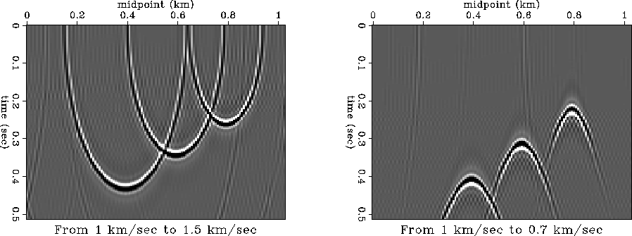
Figure ![[*]](http://sepwww.stanford.edu/latex2html/cross_ref_motif.gif) shows impulse responses of prestack velocity
continuation. The input for producing this figure was a time-migrated
constant-offset section, corresponding to an offset of 1 km and a
constant migration velocity of 1 km/s. In full accordance with the
theory Fomel (1996), three spikes in the input section
transformed into shifted ellipsoids after continuation to a higher
velocity and into shifted hyperbolas after continuation to a smaller
velocity.
shows impulse responses of prestack velocity
continuation. The input for producing this figure was a time-migrated
constant-offset section, corresponding to an offset of 1 km and a
constant migration velocity of 1 km/s. In full accordance with the
theory Fomel (1996), three spikes in the input section
transformed into shifted ellipsoids after continuation to a higher
velocity and into shifted hyperbolas after continuation to a smaller
velocity.
velimp
Figure 1 Impulse responses of prestack velocity
continuation. Left plot: continuation from 1 km/s to 1.5 km/s.
Right plot: continuation from 1 km/s to 0.7 km/s. Both plots
correspond to the offset of 1 km.


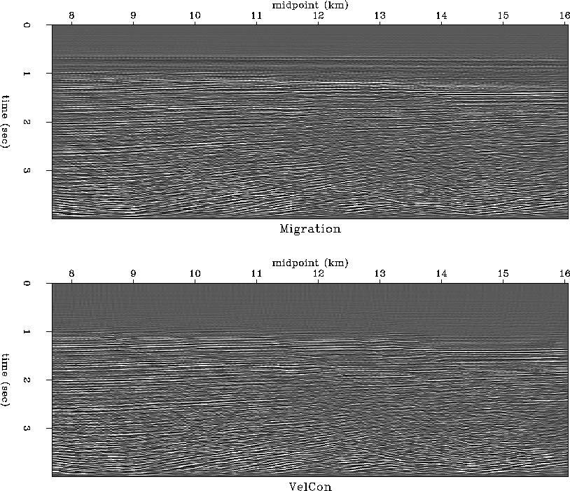
Figure ![[*]](http://sepwww.stanford.edu/latex2html/cross_ref_motif.gif) compares the result of a constant-velocity
prestack migration with the velocity of 1.8 km/s, applied to the
infamous Gulf of Mexico dataset from Basic Earth Imaging
Claerbout (1995) and the result of velocity continuation to the
same velocity from a migration with a smaller velocity of 1.3 km/s.
The differences in the top part of the images are explained by
differences in muting. In the first case, muting was applied after
migration, and in the second case, muting was applied prior to
velocity continuation. The other parts of the sections look very
similar, as expected from the theory.
compares the result of a constant-velocity
prestack migration with the velocity of 1.8 km/s, applied to the
infamous Gulf of Mexico dataset from Basic Earth Imaging
Claerbout (1995) and the result of velocity continuation to the
same velocity from a migration with a smaller velocity of 1.3 km/s.
The differences in the top part of the images are explained by
differences in muting. In the first case, muting was applied after
migration, and in the second case, muting was applied prior to
velocity continuation. The other parts of the sections look very
similar, as expected from the theory.
velmigr
Figure 2 Top: The Gulf of Mexico dataset
from BEI after prestack migration with the constant velocity
of 1.8 km/s. Bottom: The same data after after velocity continuation
from 1.3 km/s to 1.8 km/s.


Velocity continuation creates a time-midpoint-velocity cube
(four-dimensional for 3-D data), which we can use for picking RMS
velocities in the same way as we would use the result of
common-midpoint or common-reflection-point velocity analysis. The
important difference is that velocity continuation provides an optimal
focusing of the reflection energy by properly taking into account both
vertical and lateral movements of reflector images with changing
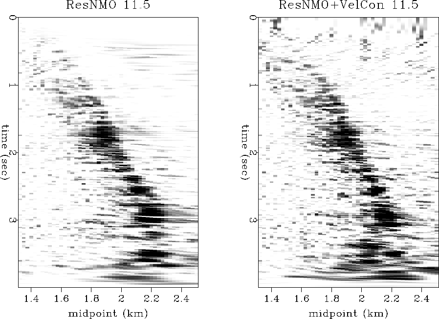
migration velocity. Figure ![[*]](http://sepwww.stanford.edu/latex2html/cross_ref_motif.gif) compares velocity spectra
(semblance panels) at a CRP location of about 11.5 km after residual
NMO and after prestack velocity continuation. Although the overall
difference between the two panels is small, the velocity continuation
panel shows a noticeably better focusing, especially in the region of
conflicting dips between 1 and 2 seconds. The next section discusses
the velocity picking step in more details.
compares velocity spectra
(semblance panels) at a CRP location of about 11.5 km after residual
NMO and after prestack velocity continuation. Although the overall
difference between the two panels is small, the velocity continuation
panel shows a noticeably better focusing, especially in the region of
conflicting dips between 1 and 2 seconds. The next section discusses
the velocity picking step in more details.
consmb
Figure 3 Velocity spectra around 11.5 km CRP after
residual NMO (left) and after prestack velocity continuation
(right). The right plot shows improved focusing in the region between
1 and 2 seconds.


Next: Velocity picking and slicing
Up: Fomel: Velocity continuation
Previous: Introduction
Stanford Exploration Project
4/20/1999


![[*]](http://sepwww.stanford.edu/latex2html/cross_ref_motif.gif) shows impulse responses of prestack velocity
continuation. The input for producing this figure was a time-migrated
constant-offset section, corresponding to an offset of 1 km and a
constant migration velocity of 1 km/s. In full accordance with the
theory Fomel (1996), three spikes in the input section
transformed into shifted ellipsoids after continuation to a higher
velocity and into shifted hyperbolas after continuation to a smaller
velocity.
shows impulse responses of prestack velocity
continuation. The input for producing this figure was a time-migrated
constant-offset section, corresponding to an offset of 1 km and a
constant migration velocity of 1 km/s. In full accordance with the
theory Fomel (1996), three spikes in the input section
transformed into shifted ellipsoids after continuation to a higher
velocity and into shifted hyperbolas after continuation to a smaller
velocity.

![[*]](http://sepwww.stanford.edu/latex2html/cross_ref_motif.gif) compares the result of a constant-velocity
prestack migration with the velocity of 1.8 km/s, applied to the
infamous Gulf of Mexico dataset from Basic Earth Imaging
Claerbout (1995) and the result of velocity continuation to the
same velocity from a migration with a smaller velocity of 1.3 km/s.
The differences in the top part of the images are explained by
differences in muting. In the first case, muting was applied after
migration, and in the second case, muting was applied prior to
velocity continuation. The other parts of the sections look very
similar, as expected from the theory.
compares the result of a constant-velocity
prestack migration with the velocity of 1.8 km/s, applied to the
infamous Gulf of Mexico dataset from Basic Earth Imaging
Claerbout (1995) and the result of velocity continuation to the
same velocity from a migration with a smaller velocity of 1.3 km/s.
The differences in the top part of the images are explained by
differences in muting. In the first case, muting was applied after
migration, and in the second case, muting was applied prior to
velocity continuation. The other parts of the sections look very
similar, as expected from the theory.

![[*]](http://sepwww.stanford.edu/latex2html/cross_ref_motif.gif) compares velocity spectra
(semblance panels) at a CRP location of about 11.5 km after residual
NMO and after prestack velocity continuation. Although the overall
difference between the two panels is small, the velocity continuation
panel shows a noticeably better focusing, especially in the region of
conflicting dips between 1 and 2 seconds. The next section discusses
the velocity picking step in more details.
compares velocity spectra
(semblance panels) at a CRP location of about 11.5 km after residual
NMO and after prestack velocity continuation. Although the overall
difference between the two panels is small, the velocity continuation
panel shows a noticeably better focusing, especially in the region of
conflicting dips between 1 and 2 seconds. The next section discusses
the velocity picking step in more details.
