 |
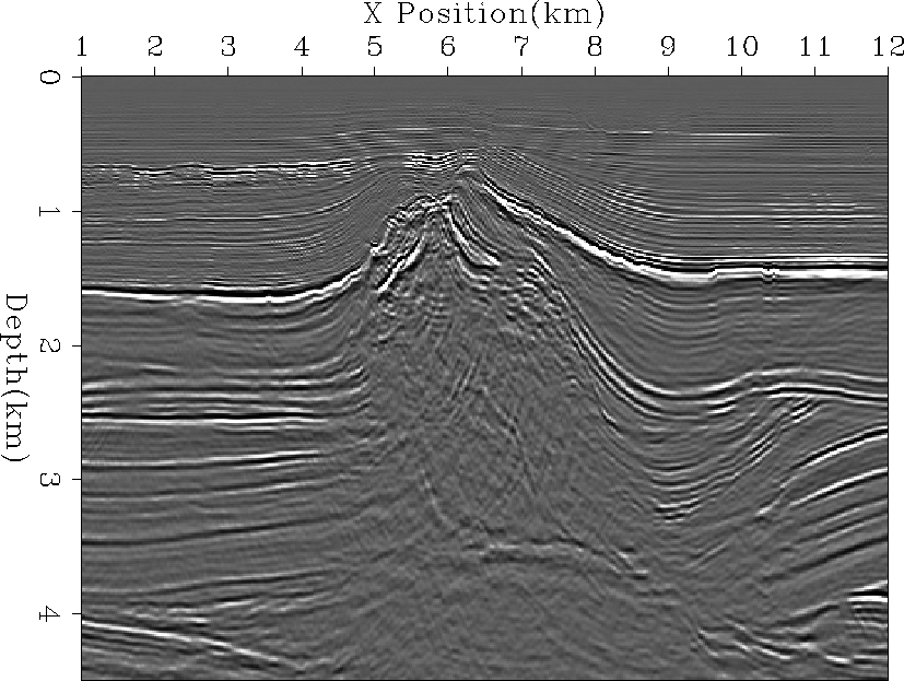
Figure 4 Migration result using the velocity from Figure 3
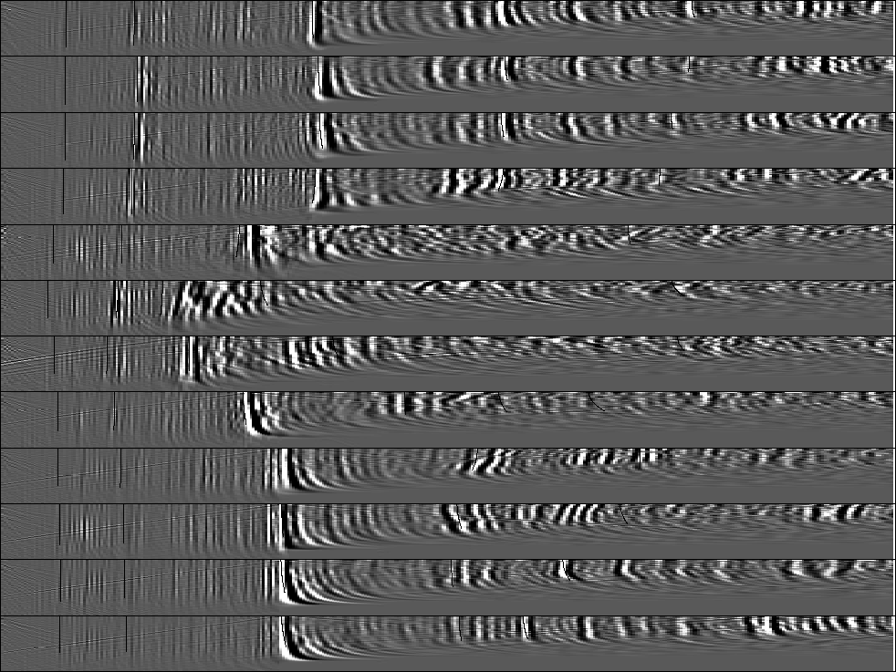
We began by migrating the data with the velocity in Figure 3. As Figure 4 shows we have some artifacts in the right portion of the migrated image due to the sharp boundary in the initial velocity model. The salt is poorly defined. We don't have a coherent reflection for the top of the salt, we have very little of the salt edges, and have a non-continuous salt bottom. Reflections to the left of the salt body do not continue all the way to the salt edge. In addition, we have little resolution below the fault at 10 km. If we look at the angle gathers for the initial migration, Figure 5, we can see significant moveout errors.
 |
 |
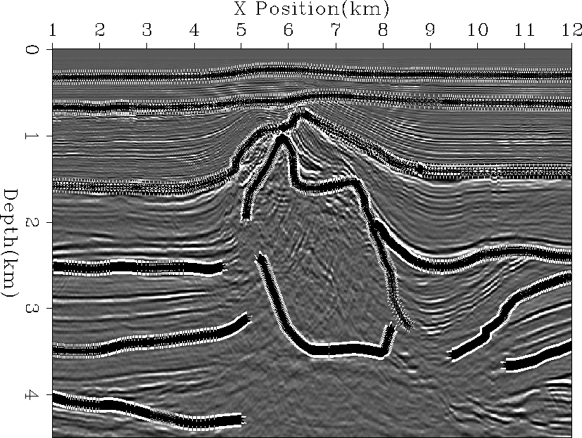
Using the initial migrated image we chose 11 reflectors to perform tomography with (Figure 6). To constrain the upper portion of the model we chose the water bottom reflection and two reflectors above the salt. We picked the salt top and salt bottom and three reflectors on both sides of the salt body.
 |
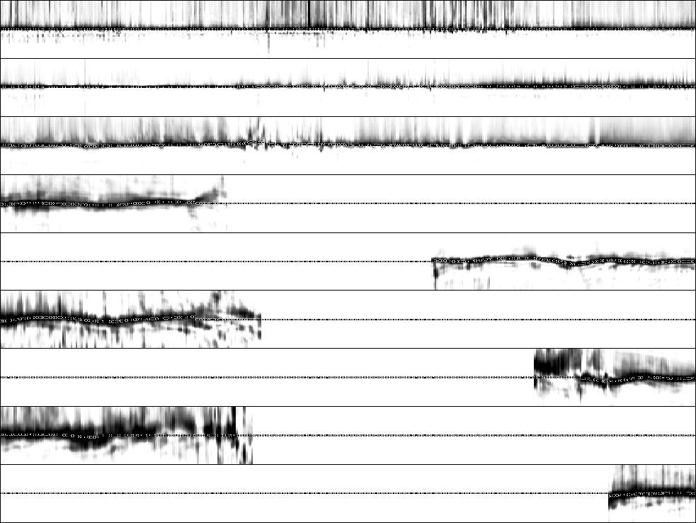
We then performed moveout analysis using equation (6). We selected the semblance at each reflector, Figure 7, and found a smooth curve using fitting goals (9). Overlaid on Figure 7 are the smooth picks used in our back projection operator. The top two reflectors have have almost no moveout errors. The remaining reflectors all have some residual moveout errors that our tomography can attempt to resolve.
 |