


To construct the steering filters we used the nine non-salt reflectors shown in Figure 6. We calculated the dip along each reflector and then smoothly interpolated between the reflectors (Figure 8).
|
amp-vel0
Figure 8 The dip field used for the first iteration of tomography. | 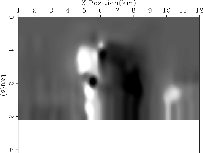 |


With the picked reflectors we have very few rays passing through the salt. As a result the smoothing fitting goal (the second goal in (4)) dominates. Instead of constant or little variation in the salt we see dramatic changes. To avoid this geologically unreasonable behavior we did not allow the velocity to change in the region delineated by our two salt reflectors.