


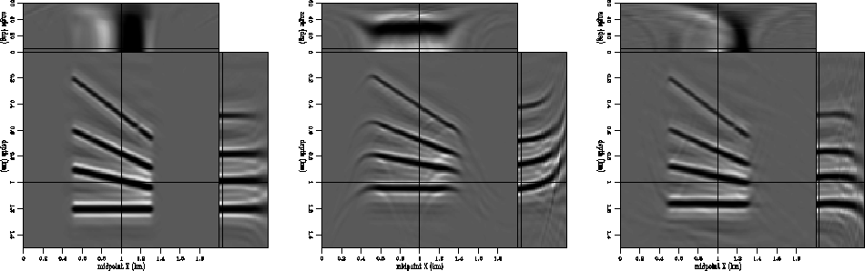
The left panel of Figure 2 shows the result of migration with the correct velocity, while the middle panel shows the result of migration with a scaled version of the original, and the right panel shows the result of residual migration using the correct velocity ratio. The flat reflectors are all restored to their original position, and the angle-domain common-image gathers are flat, indicating correct migration.
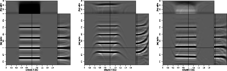
Figure 3 depicts a more complex model. In this case, the reflectors have different dips, and the velocity is variable and identical to the one in the preceding case (Figure 1). Again, the left panel shows the migration result with the correct velocity, the middle panel the result of migration with an incorrect velocity, and the right panel the result of residual migration with the correct velocity ratio. The reflectors are restored to their correct position and the angle-domain common-image gathers are flat.
 |


 |
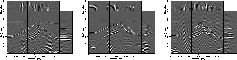 |
The next synthetic example is represented by an image around a salt body. As in the preceding examples, the left panel of Figure 4 shows the result of migration with the correct velocity, in the middle panel the result of migration with an incorrect velocity, and in the right panel, the result of residual migration with the correct velocity ratio. Again, we can conclude that prestack Stolt residual migration is able to recover the correct image, even when the velocity map is not constant. We can, therefore, apply the procedure to a much more complex seismic image obtained from data recorded over a North Sea salt dome.