


In this section, we demonstrate the method on a synthetic example. The reflectivity model (Figure 1) consists of two flat reflectors surrounding a set of reflectors dipping at 45 degrees.
|
rr
Figure 1 Reflectivity model. | 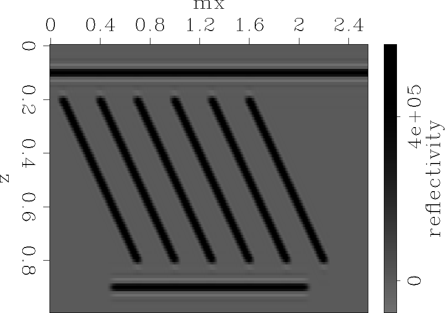 |


The background velocity (Figure 2) is characterized by strong lateral variation to provide a somewhat complex background wavefield.
|
s1
Figure 2 Background slowness model. | 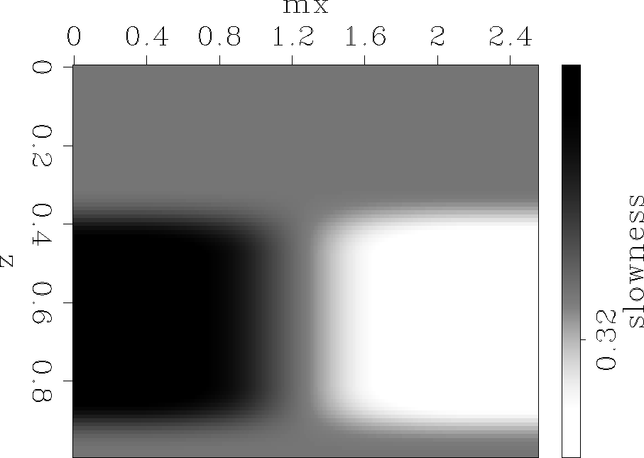 |
The image perturbation (Figure 3) consists of a rectangular block in the upper part of the section, which creates perturbations in the image both on the flat and on the dipping reflectors. We change the magnitude of this anomaly from small values that satisfy the Born approximation, to high values that clearly violate the linear assumptions.
|
ds
Figure 3 Slowness perturbation. | 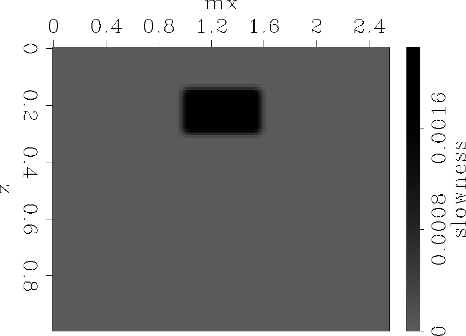 |
We use the true slowness to model the data, and then we use the background slowness to obtain the reference image and the reference wavefield. From the slowness perturbation, we use the forward WEMVA operator to create the ideal image perturbation (Figure 4). Backprojection by the adjoint WEMVA operator gives the slowness update in Figure 5, and inversion gives the slowness in Figure 6.
|
di.wei.01
Figure 4 Ideal image perturbation obtained by the forward WEMVA operator. | 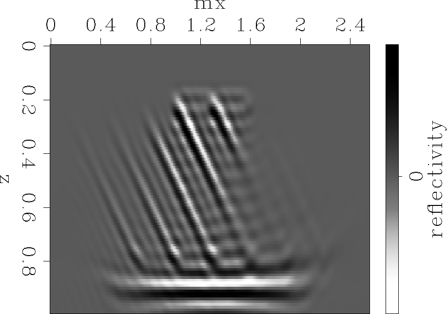 |
|
bds.wei.01
Figure 5 Slowness backprojection obtained from the ideal image perturbation using the adjoint WEMVA operator. | 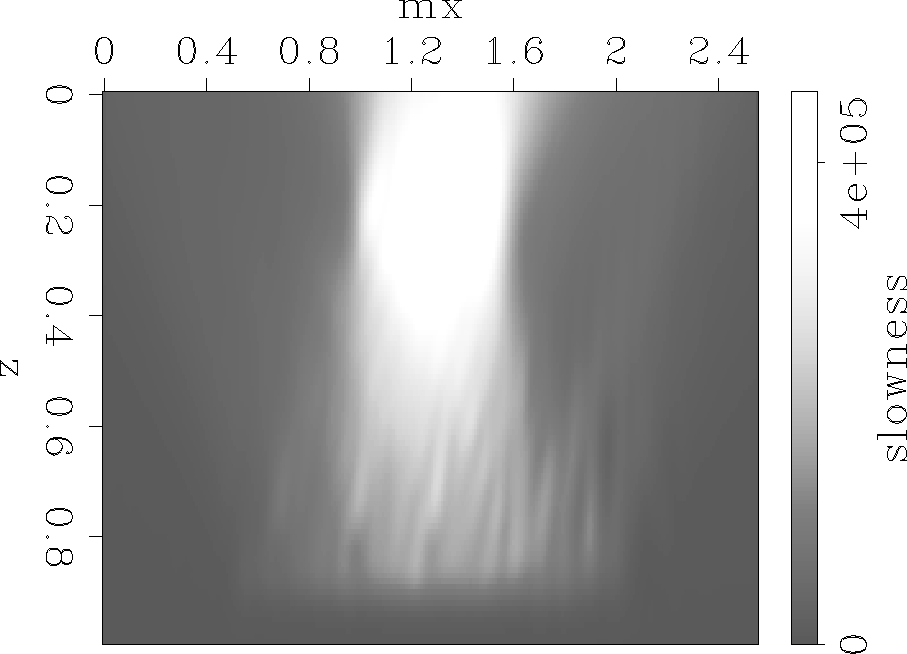 |
|
ids.wei.01
Figure 6 Slowness inversion obtained from the ideal image perturbation using the WEMVA operator. | 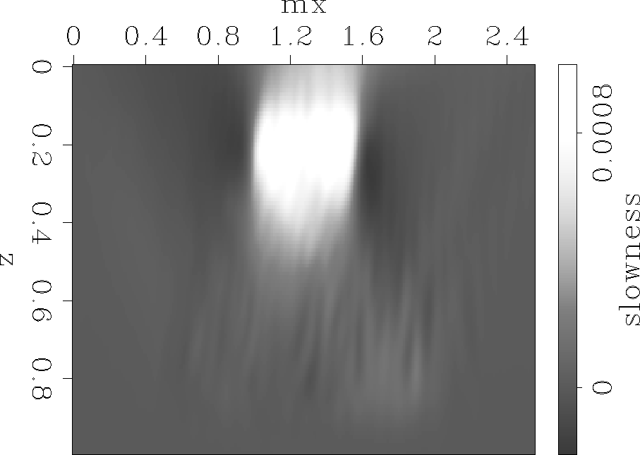 |
Figures 4 and 5 represent the benchmark against which we want to compare our new image perturbation method.
Figure 7 represents the image perturbation created
using Equation (12) where we consider that ![]() . Of course,
this is not our image perturbation, but it only gives us a rough idea
of how we should pick the actual perturbation from after weighting with
. Of course,
this is not our image perturbation, but it only gives us a rough idea
of how we should pick the actual perturbation from after weighting with ![]() .As expected, the magnitude of this component of the image increases
with depth.
.As expected, the magnitude of this component of the image increases
with depth.
|
di.ana.full
Figure 7 Image perturbation produced by Equation (12). The magnitude of the perturbation increases with depth. | 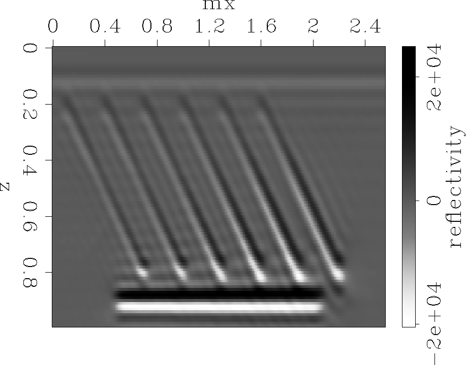 |
Next we multiply the image in Figure 7
with the ![]() weight (Figure 8) and obtain an image
perturbation (Figure 9) which is comparable
in shape and magnitude with the ideal perturbation
(Figure 4).
Backprojection by the adjoint WEMVA operator gives the slowness update in
Figure 10, and inversion gives the slowness in
Figure 11.
weight (Figure 8) and obtain an image
perturbation (Figure 9) which is comparable
in shape and magnitude with the ideal perturbation
(Figure 4).
Backprojection by the adjoint WEMVA operator gives the slowness update in
Figure 10, and inversion gives the slowness in
Figure 11.
|
mask
Figure 8 |  |
|
di.ana.01
Figure 9 Analytical image perturbation obtained by multiplication of the image in Figure 7 with the weight in Figure 8. | 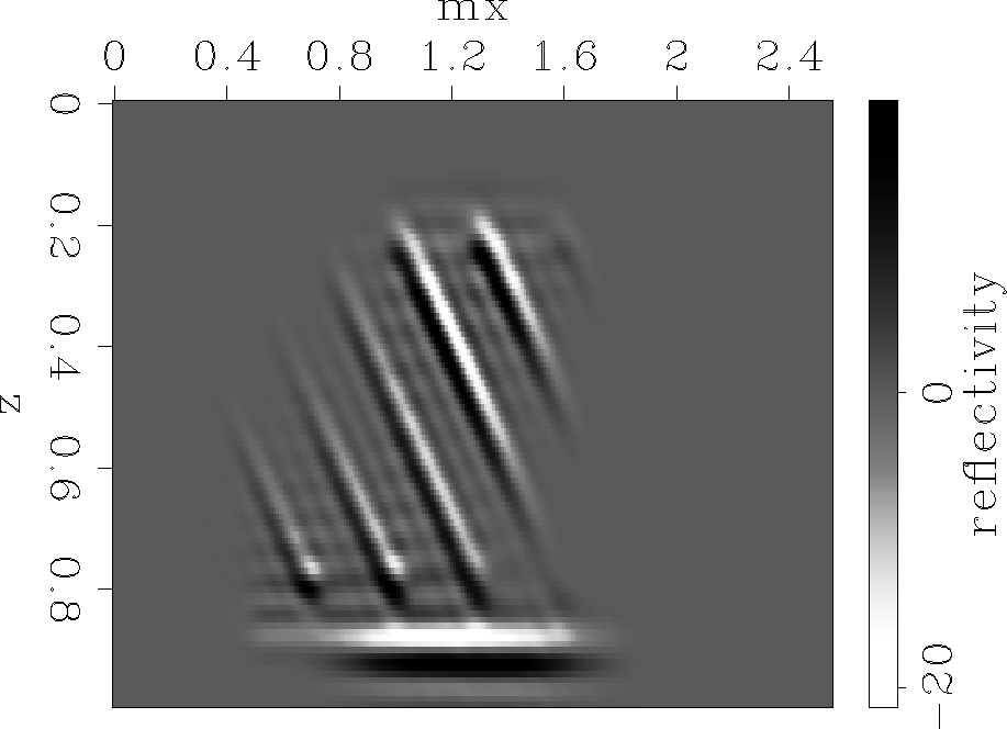 |
|
bds.ana.01
Figure 10 Slowness backprojection obtained from the analytical image perturbation using the adjoint WEMVA operator. | 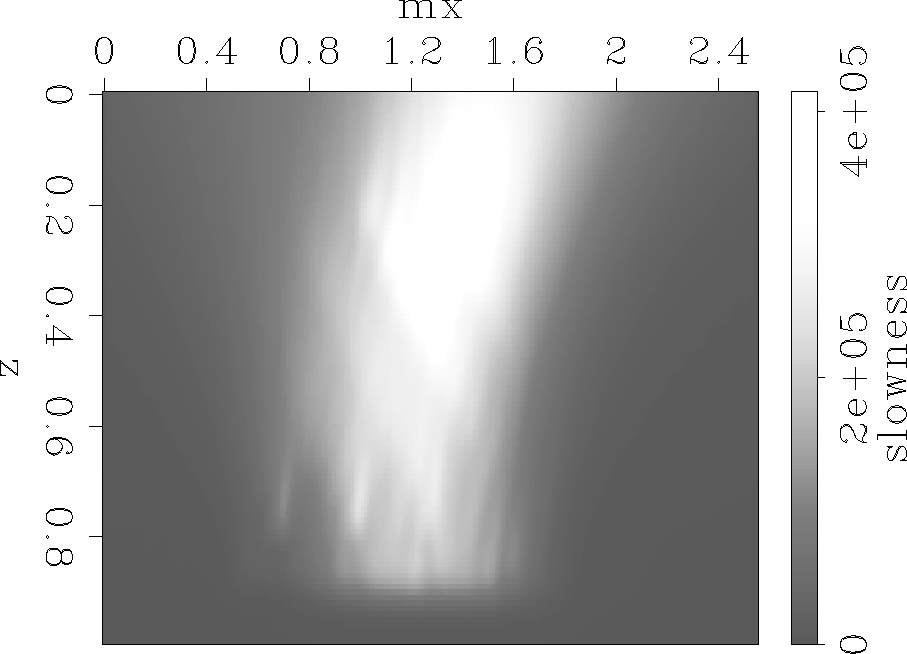 |
|
ids.ana.01
Figure 11 Slowness inversion obtained from the analytical image perturbation using the WEMVA operator. | 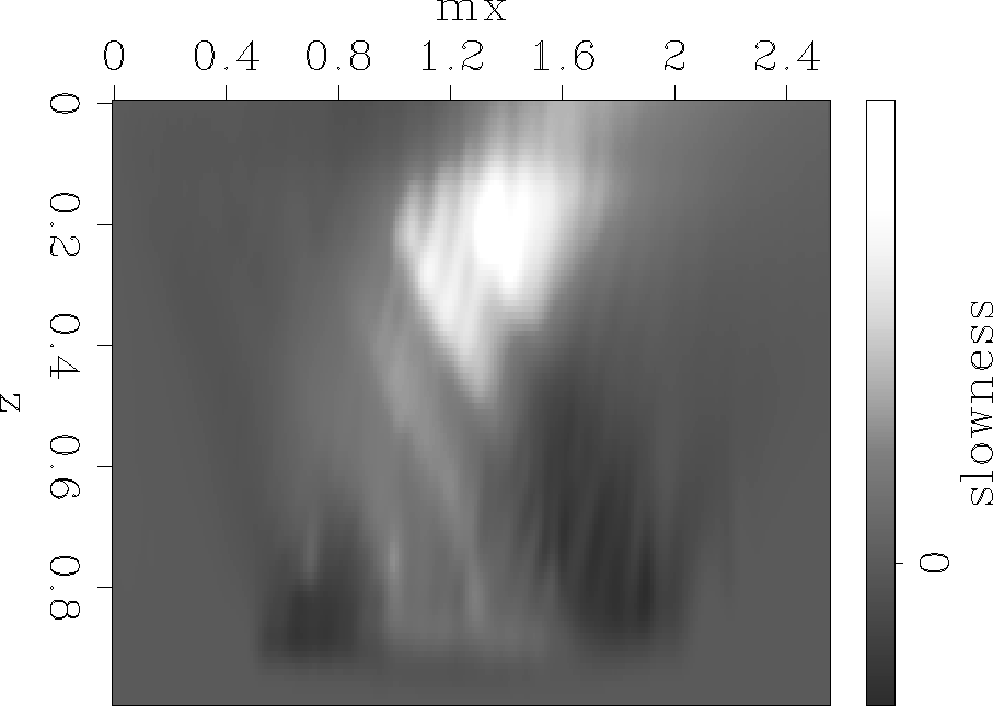 |
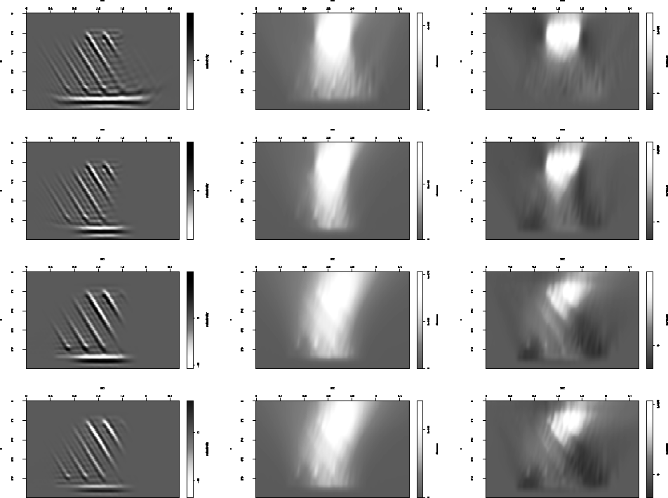
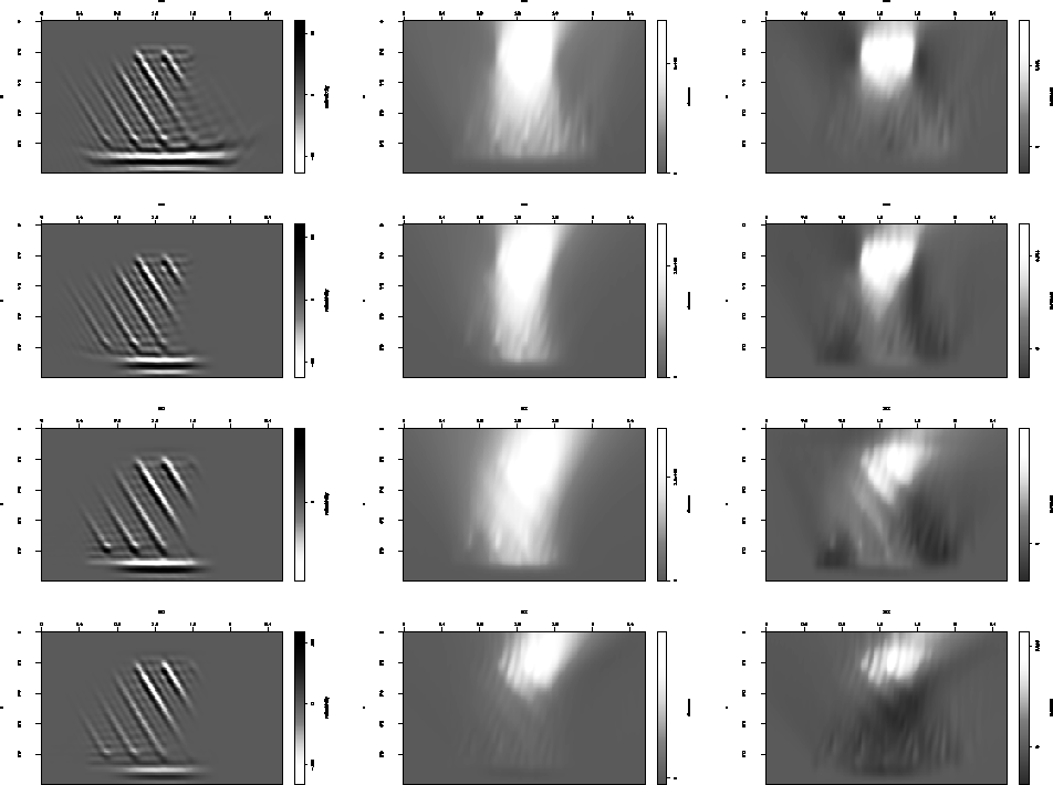
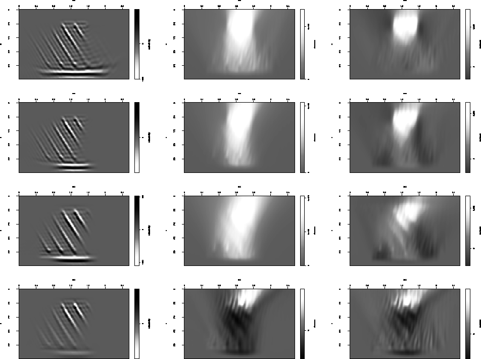
Finally, Figures 12, 13, and 14 are comparisons of the various methods used to compute the image perturbation, and the corresponding slowness model. All figures are presented in landscape mode and have three columns and four rows.
Each of the Figures 12, 13, and
14 corresponds to a different magnitude of the slowness
anomaly, everything else remaining unchanged. The main comparison is
between rows 2 and 3 of the composite image. We can observe that as we
increase the magnitude of the anomaly, the shapes of ![]() and
and ![]() remain
roughly unchanged, although the magnitudes of both the image and slowness
perturbations increase. Since, by construction, we obey the Born
approximation, we do not observe any out-of-phase effects.
remain
roughly unchanged, although the magnitudes of both the image and slowness
perturbations increase. Since, by construction, we obey the Born
approximation, we do not observe any out-of-phase effects.
In contrast, when we compare rows 3 and 4, that is our new method and
the PSRM approach, we observe that, for the small anomalies, the image and
slowness perturbations are very similar, but at high values of the anomaly,
the PSRM ![]() gets out of phase with respect to the background wavefield,
and therefore the backprojected or inverted
gets out of phase with respect to the background wavefield,
and therefore the backprojected or inverted ![]() either cancels or changes
sign altogether. This is exactly the kind of effect we are trying to
avoid using our new approach.
either cancels or changes
sign altogether. This is exactly the kind of effect we are trying to
avoid using our new approach.
 |
 |
 |