

Next: LEAST-SQUARES INVERSION
Up: IMPROVING THE OPERATOR BY
Previous: IMPROVING THE OPERATOR BY
The same synthetic model (Figure ![[*]](http://sepwww.stanford.edu/latex2html/cross_ref_motif.gif) ) that we used
in the previous section is used here.
The wavefield recorded on the irregular topography
in Figure
) that we used
in the previous section is used here.
The wavefield recorded on the irregular topography
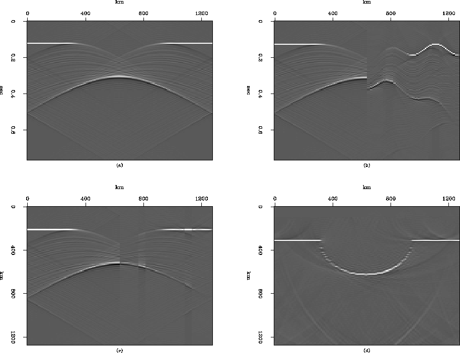
in Figure ![[*]](http://sepwww.stanford.edu/latex2html/cross_ref_motif.gif) (b) clearly demonstrates
the effect of the filter.
The wavefield traveling vertically does not differ from the
result of the first scheme,
but the wavefield traveling with some stepout shows differences.
In Figure
(b) clearly demonstrates
the effect of the filter.
The wavefield traveling vertically does not differ from the
result of the first scheme,
but the wavefield traveling with some stepout shows differences.
In Figure ![[*]](http://sepwww.stanford.edu/latex2html/cross_ref_motif.gif) (b), the right limb of the bow-tie
shows more pronounced amplitude change
which depends on the slope of the surface topography.
Locations with the same slope as the stepout of the wavefield
does not differ from the result of
the first scheme (Figure
(b), the right limb of the bow-tie
shows more pronounced amplitude change
which depends on the slope of the surface topography.
Locations with the same slope as the stepout of the wavefield
does not differ from the result of
the first scheme (Figure ![[*]](http://sepwww.stanford.edu/latex2html/cross_ref_motif.gif) (b)) but
the amplitude has been significantly reduced at the locations
with the opposite slope of the stepout of the wavefield.
(b)) but
the amplitude has been significantly reduced at the locations
with the opposite slope of the stepout of the wavefield.
From the result of the migration in Figure ![[*]](http://sepwww.stanford.edu/latex2html/cross_ref_motif.gif) (d),
we can see the noise is suppressed significantly.
Comparing to Figure
(d),
we can see the noise is suppressed significantly.
Comparing to Figure ![[*]](http://sepwww.stanford.edu/latex2html/cross_ref_motif.gif) (d),
the datumed result in the Figure
(d),
the datumed result in the Figure ![[*]](http://sepwww.stanford.edu/latex2html/cross_ref_motif.gif) (c)
has also improved.
The datumed wavefield in Figure
(c)
has also improved.
The datumed wavefield in Figure ![[*]](http://sepwww.stanford.edu/latex2html/cross_ref_motif.gif) (c)
still displays the effect of the irregular topography.
There is a big amplitude change at the center and
there is a fluctuation of the
amplitude along the surface on the right half of the wavefield.
This amplitude change along the surface can be explained by
the aperture change along the surface caused by the irregular
topography.
The valley shape topography on the surface will have more aperture
compared to the peak shape topography.
(c)
still displays the effect of the irregular topography.
There is a big amplitude change at the center and
there is a fluctuation of the
amplitude along the surface on the right half of the wavefield.
This amplitude change along the surface can be explained by
the aperture change along the surface caused by the irregular
topography.
The valley shape topography on the surface will have more aperture
compared to the peak shape topography.
dataimgtp2
Figure 9 Synthetic examples using the second scheme.
(a) : Wave field recorded at the depth level
at the bottom of the irregular topography.
(b) : Wave field recorded at the irregular surface.
(c) : Wave field extrapolated back to the bottom
of the topography during the migration.
(d) : The subsurface image obtained by the migration
of the data in Figure ![[*]](http://sepwww.stanford.edu/latex2html/cross_ref_motif.gif) (b).
[ Compare to Figure
(b).
[ Compare to Figure ![[*]](http://sepwww.stanford.edu/latex2html/cross_ref_motif.gif) . ]
. ]


Next: LEAST-SQUARES INVERSION
Up: IMPROVING THE OPERATOR BY
Previous: IMPROVING THE OPERATOR BY
Stanford Exploration Project
11/17/1997
![[*]](http://sepwww.stanford.edu/latex2html/cross_ref_motif.gif) (d),
we can see the noise is suppressed significantly.
Comparing to Figure
(d),
we can see the noise is suppressed significantly.
Comparing to Figure ![[*]](http://sepwww.stanford.edu/latex2html/cross_ref_motif.gif) (d),
the datumed result in the Figure
(d),
the datumed result in the Figure ![[*]](http://sepwww.stanford.edu/latex2html/cross_ref_motif.gif) (c)
has also improved.
The datumed wavefield in Figure
(c)
has also improved.
The datumed wavefield in Figure ![[*]](http://sepwww.stanford.edu/latex2html/cross_ref_motif.gif) (c)
still displays the effect of the irregular topography.
There is a big amplitude change at the center and
there is a fluctuation of the
amplitude along the surface on the right half of the wavefield.
This amplitude change along the surface can be explained by
the aperture change along the surface caused by the irregular
topography.
The valley shape topography on the surface will have more aperture
compared to the peak shape topography.
(c)
still displays the effect of the irregular topography.
There is a big amplitude change at the center and
there is a fluctuation of the
amplitude along the surface on the right half of the wavefield.
This amplitude change along the surface can be explained by
the aperture change along the surface caused by the irregular
topography.
The valley shape topography on the surface will have more aperture
compared to the peak shape topography.
