The local ray-tracing method propagates a wavefront locally through triangular cells of linearly varying velocities by following local rays. Because the whole process of wavefront propagation involves tracing many local rays, it is necessary to have an efficient ray-tracing algorithm. Fortunately, the analytical solutions to the ray equations for a linearly varying velocity field are well known, and the analytical solutions of R and J for such a velocity field are also known. Here I merely quote the results. The details of the derivations can be found in Telford et. al. (1976) and Cervený (1981abc).
Suppose we know the attributes of
a wavefront, ![]() ,
at an initial point (x0,z0). By tracing a ray, we can find the attributes
of the wavefront,
,
at an initial point (x0,z0). By tracing a ray, we can find the attributes
of the wavefront, ![]() , at an arbitrary
point (x,z) on the ray.
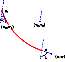
In a linearly varying velocity field, the two components of the velocity
gradient are constant, (vx,vz).
It is known that in such a velocity field
the ray follows
a circular trajectory. The traveltime is determined by integrating the inverse
of velocity along the ray, which yields
, at an arbitrary
point (x,z) on the ray.
In a linearly varying velocity field, the two components of the velocity
gradient are constant, (vx,vz).
It is known that in such a velocity field
the ray follows
a circular trajectory. The traveltime is determined by integrating the inverse
of velocity along the ray, which yields
| |
(4) |
![[*]](http://sepwww.stanford.edu/latex2html/cross_ref_motif.gif) .
It can be shown that
.
It can be shown that
 |
(5) |
| (6) |
 |
(7) |
| |
(8) |
Cervený (1981a) shows that in a velocity field of zero second order spatial derivatives, the curvature radius of a wavefront at a point on a ray is linearly proportional to the integration of the velocity field along the ray. Because a linearly varying velocity field has zero second-order spatial derivatives, the integration of the velocity along the circular ray path gives
| |
(9) |
| |
(10) |
|
vpraytrc
Figure 2 Ray-tracing in a linearly varying velocity field. The dash arrow shows the direction of the velocity gradient. The solid arrows show the directions of traveltime gradients that are tangential to the ray. Ray angles are measured between the direction of the velocity gradient and the directions of the ray. |  |
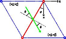
When a ray reaches the boundary of two adjacent triangular cells,
the phase matching method can be used to trace the ray across
the boundary (Cervený, 1981c).
Traveltime ![]() and take-off angle
and take-off angle ![]() are always continuous
across the boundary. Because of the continuous
velocity representation, there is no discontinuity of velocity across
the boundary. Therefore traveltime gradient (u,w) and geometrical spreading factor
J are also continuous at the boundary. However,
curvature radius R is generally not continuous at the boundary
because of the change of the velocity gradient across the boundary.
Cervený (1981c) derives a general formula that relates
the curvature radii of wavefronts on the two sides of the boundary.
This general formula can be greatly simplified by considering
that the velocity field is continuous at the boundary
and that the boundary has a zero curvature. The result is
are always continuous
across the boundary. Because of the continuous
velocity representation, there is no discontinuity of velocity across
the boundary. Therefore traveltime gradient (u,w) and geometrical spreading factor
J are also continuous at the boundary. However,
curvature radius R is generally not continuous at the boundary
because of the change of the velocity gradient across the boundary.
Cervený (1981c) derives a general formula that relates
the curvature radii of wavefronts on the two sides of the boundary.
This general formula can be greatly simplified by considering
that the velocity field is continuous at the boundary
and that the boundary has a zero curvature. The result is
| (11) |
![[*]](http://sepwww.stanford.edu/latex2html/cross_ref_motif.gif) ,
, |
vpbound
Figure 3 Ray-tracing across a boundary of two triangular cells. Because the velocity is continuous at the boundary, the angle of incidence is equal to the angle of refraction. |  |
Finite difference methods propagate local wavefronts in cells of constant
velocity. Because wavefronts propagate along straight rays in a constant
velocity field, local ray-tracing is trivial. The local-plane-wave assumption
implies that ![]() . All these simplifications make
finite difference methods more efficient than the local ray-tracing method.
Of course, they also reduce the accuracy of the computations.
. All these simplifications make
finite difference methods more efficient than the local ray-tracing method.
Of course, they also reduce the accuracy of the computations.