![[*]](http://sepwww.stanford.edu/latex2html/cross_ref_motif.gif) shows a cell in a triangular grid. At two corners of
the triangular cell, the attributes of the wavefront are known to be
shows a cell in a triangular grid. At two corners of
the triangular cell, the attributes of the wavefront are known to be
A wavefront can be locally propagated by tracing local rays.
Figure ![[*]](http://sepwww.stanford.edu/latex2html/cross_ref_motif.gif) shows a cell in a triangular grid. At two corners of
the triangular cell, the attributes of the wavefront are known to be
shows a cell in a triangular grid. At two corners of
the triangular cell, the attributes of the wavefront are known to be
![]()
![]()
![]()
|
vpwftprg1
Figure 4 Local wavefront propagation when the wavefront attributes at the points a and b are associated with a common wavefront. By tracing two local rays, the wavefront attributes at the point o is determined from the wavefront attributes at the points a and b jointly. | 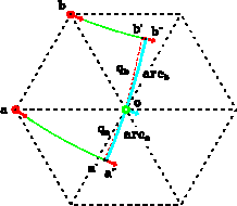 |
The procedure begins with local ray-tracing from two corners of the
triangular cell, where the attributes of wavefronts are known.
As shown in Figure ![[*]](http://sepwww.stanford.edu/latex2html/cross_ref_motif.gif) , the ray a shoots from the point a and
in the direction of the gradient vector (ua,wa), and the ray b shoots
from the point b and in the direction of the gradient vector (ub,wb).
These two rays form a ray-tube that guides the propagation of the local
wavefront passing between the points a and b.
If a point on the local wavefront
follows the wavefront propagation and
reaches the third corner of the triangle, it must cross the boundary ab and
propagate through the triangular cell. Therefore, the two local rays
are traced as if the straight-line boundary ab extends out at both ends
and the velocity field within the triangular cell extends out with
the velocity gradient being unchanged. The wavefront attributes
at any point on the rays can be calculated
by using the formulas presented in the last section.
, the ray a shoots from the point a and
in the direction of the gradient vector (ua,wa), and the ray b shoots
from the point b and in the direction of the gradient vector (ub,wb).
These two rays form a ray-tube that guides the propagation of the local
wavefront passing between the points a and b.
If a point on the local wavefront
follows the wavefront propagation and
reaches the third corner of the triangle, it must cross the boundary ab and
propagate through the triangular cell. Therefore, the two local rays
are traced as if the straight-line boundary ab extends out at both ends
and the velocity field within the triangular cell extends out with
the velocity gradient being unchanged. The wavefront attributes
at any point on the rays can be calculated
by using the formulas presented in the last section.
As shown in Figure ![[*]](http://sepwww.stanford.edu/latex2html/cross_ref_motif.gif) , the local rays a and b are traced
to the points
, the local rays a and b are traced
to the points ![]() and
and ![]() , respectively. At these two points,
the normal distances from the third corner of the triangular cell
to the rays are achieved. Let qa and qb denote the two normal distances,
and define
, respectively. At these two points,
the normal distances from the third corner of the triangular cell
to the rays are achieved. Let qa and qb denote the two normal distances,
and define
Because the normal points ![]() and
and ![]() are on the rays,
the attributes of the wavefront at these
points can be computed analytically. Let
are on the rays,
the attributes of the wavefront at these
points can be computed analytically. Let ![]() be the
curvature radius of the wavefront at the normal point
be the
curvature radius of the wavefront at the normal point ![]() .Then, the curvature center of the wavefront at the point is
.Then, the curvature center of the wavefront at the point is
 |
(12) |
 |
(13) |
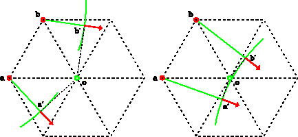
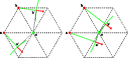
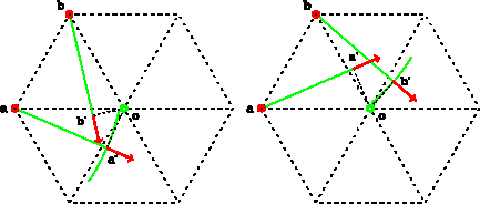
The local wavefront within the ray tube formed by the rays a and b is considered to be continuous if one of the following two sets of conditions are satisfied:
![[*]](http://sepwww.stanford.edu/latex2html/cross_ref_motif.gif) displays examples of these two cases.
If neither of the two sets of conditions hold,
the local wavefront is considered to be discontinuous.
Figure
displays examples of these two cases.
If neither of the two sets of conditions hold,
the local wavefront is considered to be discontinuous.
Figure ![[*]](http://sepwww.stanford.edu/latex2html/cross_ref_motif.gif) displays two examples.
displays two examples.
 |
 |
When the local wavefront is continuous, the attributes at the points a
and b are associated with a common wavefront.
Therefore, the curvature center of the wavefront
at the point o is estimated by averaging the curvature centers
of the wavefront
at the points ![]() and
and ![]() as follows:
as follows:
 |
(14) |
 |
(15) |
| |
(16) |
 |
(17) |
The wavefront at the point o is approximated by a local circular
wavefront of radius Ro and centered at (xo0,zo0).
As shown in Figure ![[*]](http://sepwww.stanford.edu/latex2html/cross_ref_motif.gif) , the local circular wavefront at the
point o intersects with the ray a at the point
, the local circular wavefront at the
point o intersects with the ray a at the point ![]() and the ray b at the point
and the ray b at the point ![]() . Because these two points
are on the rays, the attributes of wavefronts can be calculated
analytically. Let
. Because these two points
are on the rays, the attributes of wavefronts can be calculated
analytically. Let ![]() and
and ![]() be the traveltimes at two intersections. Because both the point
be the traveltimes at two intersections. Because both the point
![]() and the point
and the point ![]() are on the local circular wavefront defined at the
point o, the weighted average of
are on the local circular wavefront defined at the
point o, the weighted average of ![]() and
and
![]() is used to estimate the traveltime at the point o,
that is
is used to estimate the traveltime at the point o,
that is
| |
(18) |
| |
(19) |
The last parameter to be estimated is the take-off angle of the ray that reaches the point o. It can be shown that, in two-dimension,
![]()
| |
(20) |
When the local wavefront is discontinuous, the attributes
at the points a and b are associated with different
wavefronts. Therefore the local wavefront at each point should be propagated
individually. Figure ![[*]](http://sepwww.stanford.edu/latex2html/cross_ref_motif.gif) shows an example in which
the local wavefront at the point b is propagated. In this case,
the curvature center of the wavefront at the point o is assumed to
coincide with the curvature center of the wavefront at the point
shows an example in which
the local wavefront at the point b is propagated. In this case,
the curvature center of the wavefront at the point o is assumed to
coincide with the curvature center of the wavefront at the point ![]() ,
that is, xo0=xb0 and zo0=zb0. The curvature radius is then
,
that is, xo0=xb0 and zo0=zb0. The curvature radius is then
| (21) |
|
vpwftprg2
Figure 7 The local wavefront propagation when the wavefront attributes at the points a and b are associated with different wavefronts. The wavefront attributes at the point o is determined from the wavefront attributes at each point (the point b as an example) separately. | 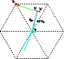 |
There are two special cases in which the rays a and b do not form
a ray-tube because of multiple arrivals. Figure ![[*]](http://sepwww.stanford.edu/latex2html/cross_ref_motif.gif) shows
examples of two such cases. In both cases, the rays a and b converge
with each other, that is
shows
examples of two such cases. In both cases, the rays a and b converge
with each other, that is
![]()
The wavefront may be diffracted at the points a and b because of
the changes of the velocity gradients in the adjacent triangular cells.
Figure ![[*]](http://sepwww.stanford.edu/latex2html/cross_ref_motif.gif) shows an example of diffraction at the point b.
Two rays that are traced with the same initial conditions at the point b
split towards two sides. The local wavefront corresponding to diffraction
is defined between two rays. The attributes of the diffracted wavefront are
computed by tracing the local ray connecting the points b and o.
shows an example of diffraction at the point b.
Two rays that are traced with the same initial conditions at the point b
split towards two sides. The local wavefront corresponding to diffraction
is defined between two rays. The attributes of the diffracted wavefront are
computed by tracing the local ray connecting the points b and o.
 |
|
vpwftprg3
Figure 9 An example of a diffracted local wavefront at the point b. | 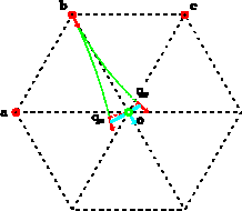 |