Next: Zhang's improved DMO
Up: DMO BY FOURIER TRANSFORM
Previous: 2-D Fourier transforms of
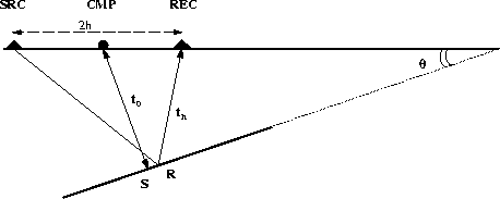
Given the geometry in Figure ![[*]](http://sepwww.stanford.edu/latex2html/cross_ref_motif.gif) we have proved in Part 1 that
we have proved in Part 1 that
| 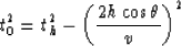 |
(10) |
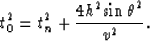
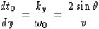
where t0 is the traveltime from CMP to the reflector and back,
th is the source-receiver traveltime, 2h is the distance
between source and receiver and v is the velocity of the medium.
Note that in this situation the reflection point R in the nonzero-offset
case differs from the actual reflection point S in the zero-offset case.
HaleDMO
Figure 12 Geometry for a dipping reflector in a constant velocity medium.
Notice that the reflection point for the nonzero-offset ray R
is different from the zero-offset reflection point S.
The dipping angle is  .
.

Hale (1984) uses equation (10) to write
| 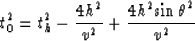 |
(11) |
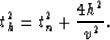
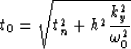
and we observe that the NMO corrected time is
| 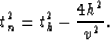 |
(12) |
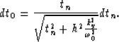
Substituting tn in equation (11) we have
|  |
(13) |
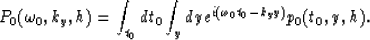
Let us consider a pressure field p(th,y,h) recorded as a
function of nonzero-offset time th, midpoint y and
offset h. In a constant-offset section we set the variable h
to a constant value, so we have a 2-D field p(th,y;h=h0).
For all the values of the offset h we have a 3-D field p(th,y;h).
We define a new field pn (tn,y,h) as
| 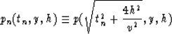 |
(14) |
obtained by replacing the value of the constant-offset traveltime th
in p(th,y,h) by its expression in equation (12)
Note that for a constant value of h this transformation amounts
to shifting a value in a trace from th to tn.
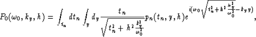
Next we define another field p0(t0,y,h) as
| 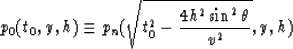 |
(15) |
obtained by replacing the value of the NMO corrected traveltime tn
in pn(tn,y,h) by its expression in equation (13).
Equation (15) is dip dependent as it contains the
variable  .The new field p0(t0,y,h) so far is unknown and further computations
are needed to determine it. However equation (15) formally
represents a mapping from a NMO corrected field to a DMO corrected field.
Remember again that in this formulation the nonzero-offset reflection point R
does not correspond to the zero-offset reflection point S.
.The new field p0(t0,y,h) so far is unknown and further computations
are needed to determine it. However equation (15) formally
represents a mapping from a NMO corrected field to a DMO corrected field.
Remember again that in this formulation the nonzero-offset reflection point R
does not correspond to the zero-offset reflection point S.
So far in equation (15) the only variable that we cannot easily
determine is so we will try to find a transformation
to express as a function of other variables.
We have in a zero-offset section

as seen in Figure .
In equation (9) we proved that for a dipping segment we have
|  |
(16) |
Now we need to Fourier transform the pressure field
p0(t0,y,h) to take advantage of the new variables  that we used in equation (16).
We have
that we used in equation (16).
We have
|  |
(17) |
We can use the mapping we defined in equation (15)
and replace p0(t0,y,h) by pn(tn,y,h) in equation
(17). By changing the variable of integration we
need to calculate the Jacobian of the transformation (13).
We have
and
|  |
(18) |
We can now rewrite equation (17) as
|  |
(19) |
which is Hale's DMO by Fourier transform.
Next: Zhang's improved DMO
Up: DMO BY FOURIER TRANSFORM
Previous: 2-D Fourier transforms of
Stanford Exploration Project
11/17/1997