 |
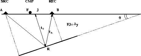
Figure 13 Geometry for a dipping reflector in a constant velocity medium. Notice that the reflection point for the nonzero-offset ray R is the same as the one for the zero-offset ray JR. The dipping angle is
Zhang (1988) observed that in Hale's DMO the reflection point in the nonzero-offset case does not coincide with the reflection point in the zero-offset case. He shows a new formula for DMO which takes into account not only a time correction but also a mid-point correction.
 |
The ![]() correction in constant velocity media as defined in Part 1
is written
correction in constant velocity media as defined in Part 1
is written

We can isolate the NMO transformation from equation (12) which is only a time-shift
![]()
 |
(20) |
![[*]](http://sepwww.stanford.edu/latex2html/cross_ref_motif.gif) the angle
the angle
![]()
The next steps follow exactly Hale's reasoning by defining another field p0(t0,y0,h), with the addition that not only the time variable is changed but also the common-midpoint variable. This accounts for the fact that the DMO transformation defined by Zhang moves the nonzero-offset reflection point to a zero-offset reflection point. Stacking after this transformation produces true common depth point gathers. In the transformation defined by Hale, the reflection point for the nonzero-offset is different from the reflection point in the zero-offset case.
The Fourier transform of the new field is
| |
(21) |
 |
(22) |
![]()

Equation (21) becomes
 |
(23) |

 |
(24) |