


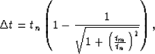
Because the DMO elliptic operator is dip-limited, it does not extend all the way up to the Earth's surface (t=0). The time spread of the impulse response is given by:
 |
(1) |
![[*]](http://sepwww.stanford.edu/latex2html/cross_ref_motif.gif) is a plot of the time spread
as a function of NMO time.
is a plot of the time spread
as a function of NMO time.
|
magic
Figure 4 Time spread of the impulse responses of DMO as a function of the impulse location, tn. The maximum time spread occurs for the input time |  |


An interesting feature of these curves is that the time spread
of the impulse responses never exceeds ![]() where
where ![]() is
is
| |
(2) |
During the process, the time slices are shifted upward until
they reach the maximum time spread. Of course, only the time slice
corresponding to the maximum time spread will have to be processed
all the way. Other time slices, like for example tn=5 seconds
(Figure ), will be processed for
the first .1 second and then pass through idle processors. Obviously,
the later time slices require less processing than the earlier ones, and
thus represent a waste of processing capacity. The following formula
gives the load balance as a function of trace length:
| |
(3) |
,
).
|
integ
Figure 5 Load balance as a function of the trace length. The optimal load balance of eighty percent corresponds to a trace length which is a function of tm (=2h/v). The bigger tm is, the later the load balance is optimal. Click on the following button to see a movie of the load balance for different values of tm. | 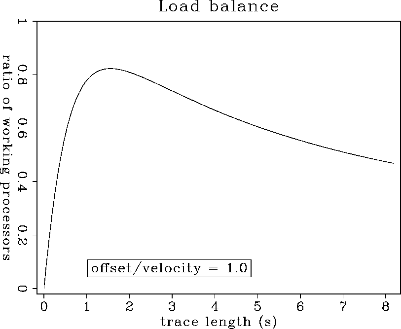 |
This algorithm allows a more efficient distribution of work between
processors than the spiral trace processing described earlier.
I implemented this algorithm for a two-dimensional model
(Figure is an output of the program) but the
run time is similar to a serial implementation of DMO (in 2-D,
trace processing is more straightforward than time slice spreading).
However, the real advantage of the method will appear in
processing 3-D land data.