

Next: TRAVELTIME AND VELOCITY ANALYSIS
Up: SEISMIC MODELING
Previous: Point-source modeling
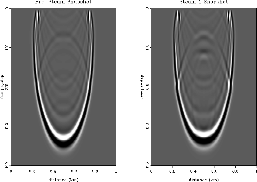
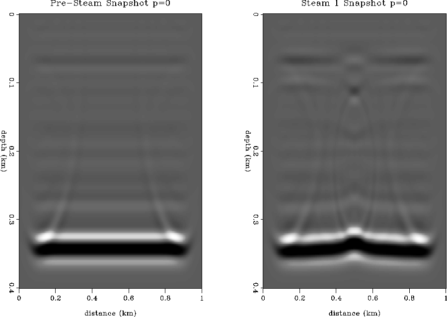
Figure 19 shows a finite difference acoustic simulation of
a plane wave source leaving the surface at vertical incidence.
The snapshot shows that the plane-wave is delayed by the steam zone
in the center at the injection well, compared to the pre-steam
synthetic. Diffractions are clearly visible at the center point.
The outer limbs of the plane wave are pulled up in time, but the
effect is too small to see in a static display.
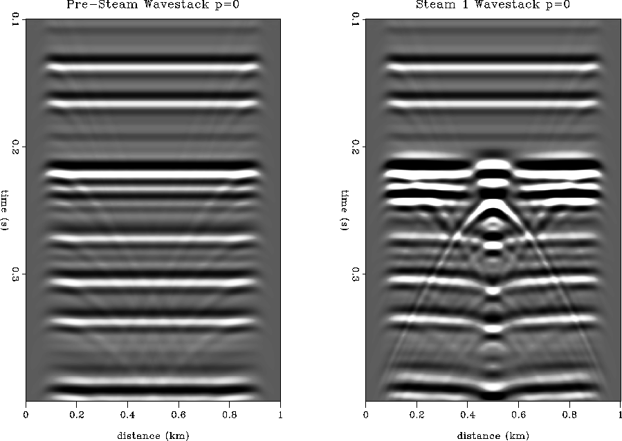
Figure 20 shows the ``wave-stack'' Schultz and Claerbout (1978)
that would have been recorded
at the surface for the vertically incident plane-wave source.
This wave-stack is similar to an NMO stack section, except it
makes no velocity assumption. Note the presence of a strong
diffraction associated with the steam zone. Also note the polarity
changes and zero crossing along the top reservoir reflection from
the steam zone to the high-pressure zone. The wave-stack
clearly shows velocity time delay and amplitude focusing below the steam zone,
and time pull-up at the survey edges beneath the portion of the reservoir
containing the high-pressure front. All of these effects are somewhat
visible in the field data sections of Figures 6
and 7.
vp123g-ann
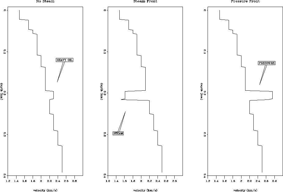
Figure 14 Velocity profiles of reservoir
containing: viscous oil (left), steam (center), and high-pressure
dissolved gas (right).
 vp1
vp1
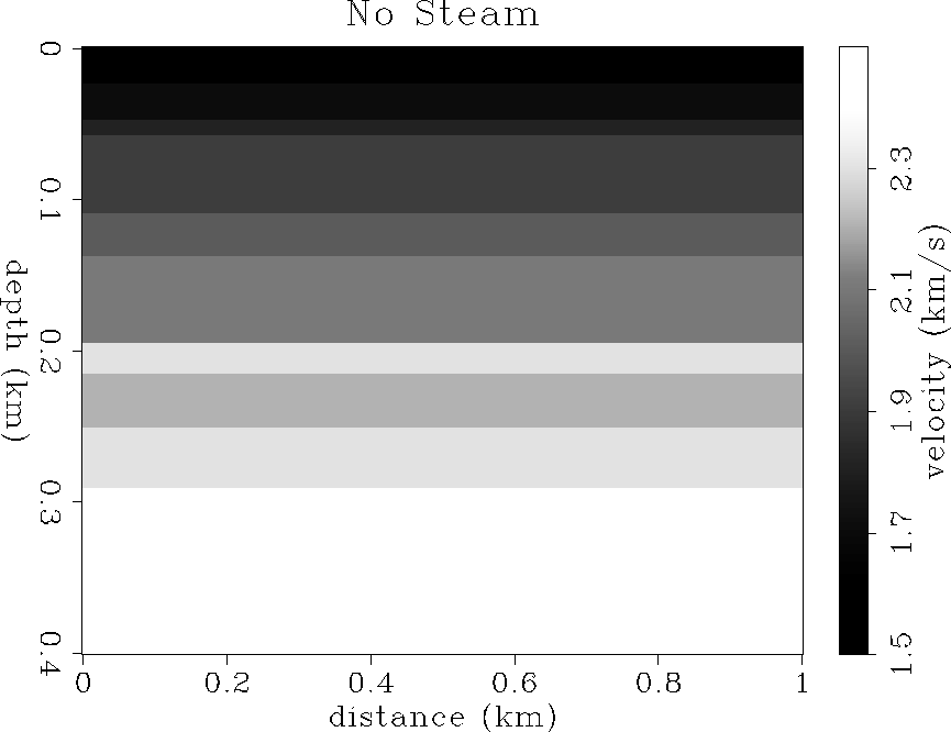
Figure 15 Velocity model before steam injection.
Heavy-oil reservoir is at 200 m depth.
 vp2
vp2
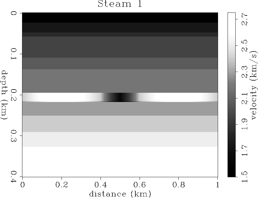
Figure 16 Velocity model after 5 months of steam
injection. Low velocity anomaly in the center (dark gray)
is due to steam, high velocity anomalies on the flanks (white)
are due to the high-pressure front.
 waves12
Figure 17 FD acoustic modeling wavefield snapshots:
before steam injection (left), during steam (right).
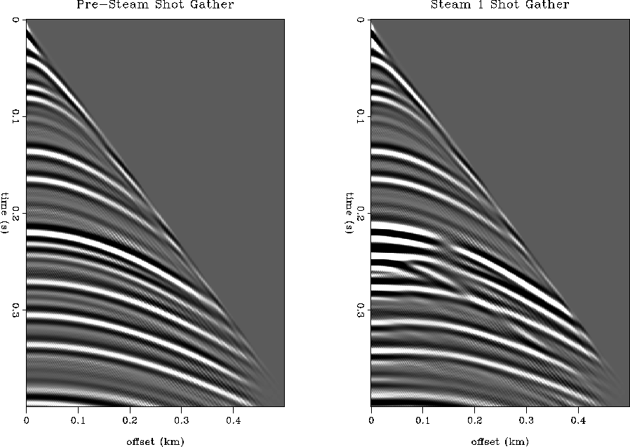
 shot12
Figure 18 FD acoustic modeled shot gathers:
before steam injection (left), during steam (right).
 pwave12
Figure 19 FD acoustic plane-wave snapshots:
before steam injection (left), during steam (right).
 wstk12
Figure 20 FD acoustic plane-wave wavestacks:
before steam injection (left), during steam (right).


Next: TRAVELTIME AND VELOCITY ANALYSIS
Up: SEISMIC MODELING
Previous: Point-source modeling
Stanford Exploration Project
11/12/1997
