


The second synthetic example illustrates the importance of computing true PS-ADCIGs. For this purpose, I use the polarity-flip characteristic of converted-wave data. In true PS-ADCIGs, the correct representation of the polarity flip should happen at zero-angle, since the zero-angle represents normal incidence, and also there is no conversion from P to S energy at normal incidence. The normal incidence location is the point in the image space that distinguish opposite particle motion; hence, the separation between positive and negative polarities.
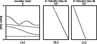
The model depicted in Figure ![[*]](http://sepwww.stanford.edu/latex2html/cross_ref_motif.gif) includes both gentle and steep dips
[panel (a)]. Both the P-velocity
and the S-velocity models, panels (b) and (c),
respectively, consist of a vertical gradient for a
non-constant
includes both gentle and steep dips
[panel (a)]. Both the P-velocity
and the S-velocity models, panels (b) and (c),
respectively, consist of a vertical gradient for a
non-constant ![]() value. The data was created with an analytical
Kirchhoff modeling scheme. The synthetic data consists
of 200 shots with a shot spacing of 50 m and 400 receivers
with a receiver spacing of 25 m. Figure
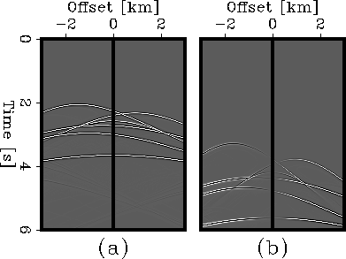
shows a single common-shot gather for this dataset.
The left panel exhibits the PP component and the
right panel the PS component.
value. The data was created with an analytical
Kirchhoff modeling scheme. The synthetic data consists
of 200 shots with a shot spacing of 50 m and 400 receivers
with a receiver spacing of 25 m. Figure
shows a single common-shot gather for this dataset.
The left panel exhibits the PP component and the
right panel the PS component.
 |


|
shot-baina
Figure 6 Single common-shot gather for the synthetic model in Figure . (a) PP gather, (b) PS gather.
|  |
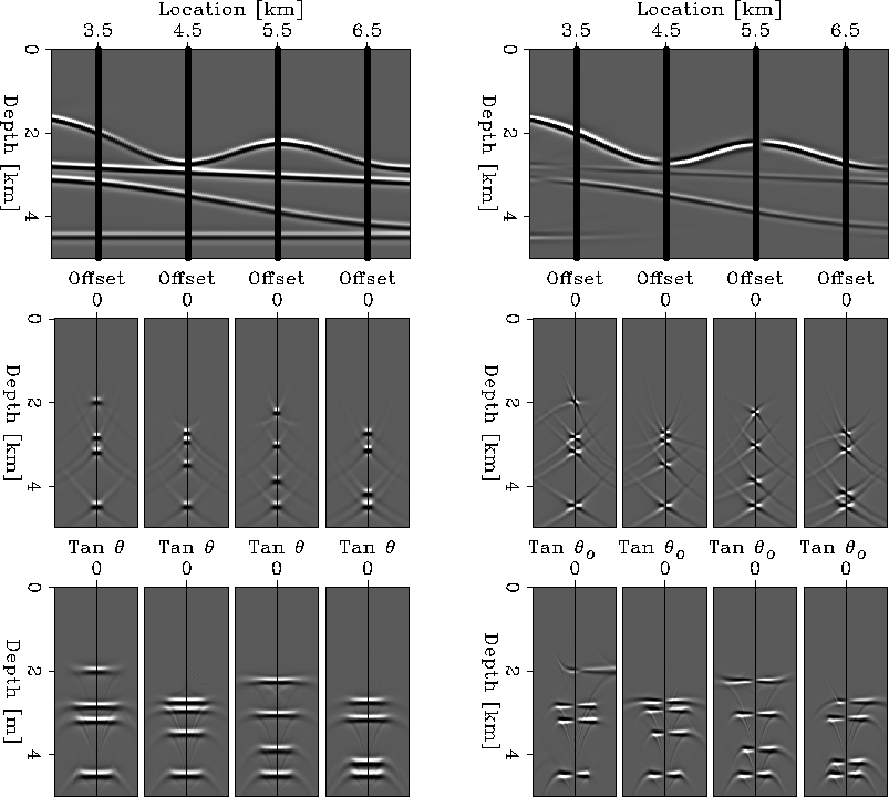
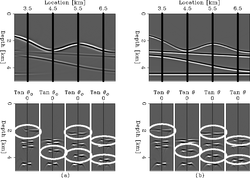
I migrated the synthetic data using a wave-equation
shot-profile migration scheme.
Figure shows the final
migration result together with four selected common-image gathers.
The top panels represent the zero subsurface-offset
section for the PP migration (left), and the PS migration (right).
Four solid lines at 3.5, 4.5, 5.5, and 6.5 km are superimposed
into both migrations.
These lines represent the locations for the four common-image
gathers underneath each migration result. The middle panels
on Figure represent the SODCIGs taken at
the position indicated by the solid lines on the migration result.
The bottom panels are the ADCIGs, both the PP-ADCIGs and the
PS-ADCIGs were obtained with the
conventional method.
The result for the PP image is accurate;
all the energy is focused at zero subsurface offset, and the
angle gathers are completely flat. This is the expected result,
since we performed the migration with the correct velocity model.
The PS results are the most interesting. First the migration section
at zero subsurface offset has positive and negative amplitudes along
the first reflection. The flat reflector has vanished because there
is no conversion from P to S energy at normal incidence. The SODCIGs
are focused at zero, and the polarity changes across the zero value.
The PS-ADCIGs are obtained with the conventional method; therefore, they
represent only the pseudo-opening angle. I follow the method
previously described and combine the PS-ADCIGs with the
image dip information (Figure ) to
obtain true PS-ADCIGs.
 |
|
step-baina
Figure 8 Local image-dip field for the third synthetic. | 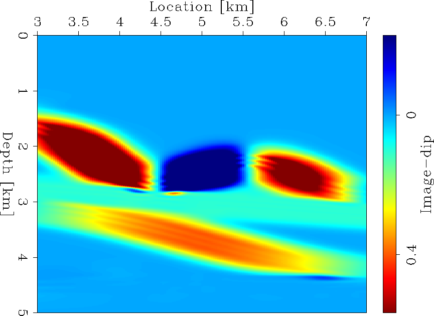 |
Figure shows the true PS-ADCIGs.
The left panel presents the PS result, the same result
that is in Figure . The top-left panel is the image
at zero subsurface offset, and the bottom-left panel shows the
PS-ADCIGs. The right panel presents the final PS result. The
top-right panel is the result of stacking in the angle domain
of the true PS-ADCIGs after correcting the polarity flip
Rosales and Rickett (2001).
The bottom-right panel shows the true PS-ADCIGs, which are taken
at the locations marked by the solid lines in the final image.
Observe the areas marked with an oval in both
the PS-ADCIGs and the
true PS-ADCIGs in Figure .
The marked areas are taken at different reflectors
for different dip values. The CIG at 3.5 km shows the most
significant change; the polarity flip is completely
corrected at zero angle, and there is larger angle
coverage, since equation stretches the
events horizontally for an accurate representation of
the half-aperture angle.
Although the changes in the
other CIGs, with respect to the polarity flip, are not that
obvious, the polarity flip is now located at zero angle.
Additionally, the events are stretched horizontally and they do
not have any residual moveout.
 |